background image

6

EN

 4  Specifications

 CAUTION

The output torque is the value measured in combination with the output torque measurement device.

When the output torque is measured by some other measuring device or combination, the value may be 
different.

The output torque and torque that occurs in screws do not match.

Use a torque wrench to check the torque generated on screws.

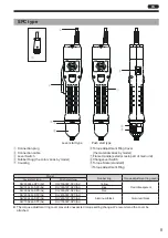
Model

Lever Start

DLV30A06L-SP(AJ)
DLV30A06L-SPC(AJ)

DLV30A12L-SP(AJ)
DLV30A12L-SPC(AJ)

DLV30A20L-SP(AJ)
DLV30A20L-SPC(AJ)

Push to Start

DLV30A06P-SP(AJ)
DLV30A06P-SPC(AJ)

DLV30A12P-SP(AJ)
DLV30A12P-SPC(AJ)

DLV30A20P-SP(AJ)
DLV30A20P-SPC(AJ)

Torque (Nm)

Low Torque Spring

0.4 to 1.6

High Torque Spring

1.2 to 3.0

Free speed (for reference) (min

-1

)

650

1200

2000

Screw Size 
(for reference)

Metric Thread (mm)

2.6 to 5.0

Tapping Screw (mm)

2.5 to 4.0

Bit Type

NK35 (HEX 6.35 mm) or NK31 (HEX 5 mm) *1

Mass (kg)

0.7 (excluding the power cord)

Power supply

230 V AC 50/60 Hz

Power Consumption (W)

45

Duty Cycle

ON time 0.5 sec./OFF time 3.5 sec.

*1  For details on how to identify between corresponding bits, see p. 3.

Model

Lever Start

DLV45A06L-SP(AJ)
DLV45A06L-SPC(AJ)

DLV45A12L-SP(AJ)
DLV45A12L-SPC(AJ)

DLV70A06L-SP(AJ)
DLV70A06L-SPC(AJ)

Push to Start

DLV45A06P-SP(AJ)
DLV45A06P-SPC(AJ)

DLV45A12P-SP(AJ)
DLV45A12P-SPC(AJ)

DLV70A06P-SP(AJ)
DLV70A06P-SPC(AJ)

Torque (Nm)

2.0 to 4.5

3.8 to 7.0 

Free speed (for reference) (min

-1

)

650

1200

650

Screw Size 
(for reference)

Metric Thread (mm)

4.5 to 6.0

5.0 to 8.0

Tapping Screw (mm)

4.0 to 5.0

4.5 to 6.0

Bit Type

NK35 (HEX 6.35 mm)

Mass (kg)

0.87 (Pistol Grip is included, excluding the power cord)

Power supply

230 V AC 50/60 Hz

Power Consumption (W)

45

Duty Cycle

ON time 0.5 sec./OFF time 3.5 sec.

Torque Measurement Device

Electric Screw Driver

DLV30A Series

DLV45A Series

DLV70A Series

Torque Checker

DLT1673A

DLT1673A

DLT1973A

Bit Joint

DLW4360

DLW4360

DLW4000

Summary of Contents for DLV30A06L-SP

Page 1: ...e Nm Low torque spring 0 4 to 1 6 2 0 to 4 5 3 8 to 7 0 High torque spring 1 2 to 3 0 Free Speed min 1 650 1200 2000 650 1200 650 Please refer to p 6 for details Please read manual carefully before yo...

Page 2: ...that Can Be Attached 3 3 Part Names 4 SP type 4 SPC type 5 4 Specifications 6 Torque scale and output torque 7 SP type signal specifications 7 5 Preparation 10 Attaching a bit 10 Attaching the suspen...

Page 3: ...ll Depending on fastening conditions screws may become loose Improper impacts could decrease product life or cause product failure Do not use the tool for anything other than screw tightening It shoul...

Page 4: ...f the SPC type This tool is only for screw fastening counter DLR5040A WE and DLR5340 WE Use it in combination with the screw fastening counter For how to use the screw fastening counter refer to the i...

Page 5: ...that Can Be Attached You can identify bits that can be attached based on the alphabet character written to the right of the serial number of the electric screwdriver 1 Serial No 1 Attachable bit shape...

Page 6: ...it 0 Changeover Switch a Torque Scale standard b Torque Adjustment Ring Model Rubber ring Torque adjustment ring cover Lever start type Push start type DLV30A06L SP AJ DLV30A06P SP AJ Yellow Resin tra...

Page 7: ...9 Torque Scale standard 0 Torque Adjustment Ring Model Rubber ring Torque adjustment ring cover Lever start type Push start type DLV30A06L SPC AJ DLV30A06P SPC AJ Yellow Resin transparent DLV30A12L SP...

Page 8: ...5 HEX 6 35 mm or NK31 HEX 5 mm 1 Mass kg 0 7 excluding the power cord Power supply 230 V AC 50 60 Hz Power Consumption W 45 Duty Cycle ON time 0 5 sec OFF time 3 5 sec 1 For details on how to identify...

Page 9: ...the signal output within the output rating Use of the tool at a voltage or current value above the rating could cause the tool to fail Do not directly connect the relay motor lamp etc to control It co...

Page 10: ...Do not directly connect the relay motor lamp etc to control It could cause the tool to fail due to surge etc generated from inductive load Before energizing make sure that the signal cables are wired...

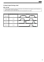
Page 11: ...rned ON while the changeover switch of forward and reverse rotation is at the neutral position When torque up occurs in the reverse rotation the torque up signal is also output Signal cable wiring col...

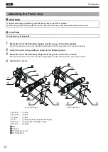
Page 12: ...ease the sleeve and make sure the bit does not come off To remove the bit pull out the bit while pulling the sleeve Attaching the suspension bail CAUTION If the suspension bail is pulled forcefully it...

Page 13: ...is turned there will be no clicking sound Recommended grease separately sold Idemitsu Kosan Co Ltd Daphne Eponex SR No 2 Showa Shell Sekiyu K K Alvania Grease S2 Cosmo Oil Co Ltd DYNAMAX No 2 1 Turn t...

Page 14: ...Grip body A and the semicircle rib of the frame handle 2 Attach the parts to the positions shown in the following figure 3 Match the rib of the Pistol Grip body B and the groove of the frame handle Ma...

Page 15: ...e If you are not sure about the grounding of the outlet request an electrical contractor to check if it is grounded When an extension cord is used use a 3 core cord that includes a ground wire SP type...

Page 16: ...value as the power supply voltage of the screw fastening counter 1 Confirm that the power supply of the screw fastening counter is OFF and connect the connection cord to the screw fastening counter 2...

Page 17: ...rs Be sure to turn ON the start switch until the electric screwdriver automatically stops Slide the changeover switch to the direction in which you want the tool to rotate and press the start switch t...

Page 18: ...n the electric driver stops release the start switch Adjusting the output torque WARNING Before adjusting the output torque always turn OFF the power CAUTION The torque scale is a standard The output...

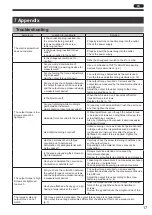
Page 19: ...increased screws are not tightened Review the screw fastening conditions Also by tightening at low speed it becomes easier to transmit torque Has initial loosening occurred Initial loosening occurs a...

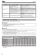
Page 20: ...nditions Also it differs by the unit p 6 Maintenance and inspection Store the tool according to the following warnings and cautions WARNING Before performing maintenance and inspection always turn off...

Page 21: ...w head could be damaged or torque may not be transmitted Replace with a new bit Main unit Check for damage cracks or breaks on the main unit Check the screws on the main unit including accessory Pisto...

Page 22: ...unter DLR5040A WE DLR5340 WE Dedicated to SPC type Counter for prevention of human error and for management of fastening 100 V AC 240 V AC SPC extension cable 3 m Dedicated to SPC type Cord that exten...

Page 23: ...5 4 5 42 DIA 42 DIA Front view DLV30A06L SP AJ SPC AJ DLV30A12L SP AJ SPC AJ DLV30A20L SP AJ SPC AJ Front view DLV30A06P SP AJ SPC AJ DLV30A12P SP AJ SPC AJ DLV30A20P SP AJ SPC AJ Side view Common to...

Reviews: