


8
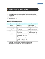
Installation Environment
Select the installation location considering the following, and get
consent from the user if needed.
①
This product should be installed indoors. If installed outdoors, the
product must be protected from direct sunlight, snow, and rain.
②
Cables must not be exposed and it is recommended that they be
buried. If this isn’t possible due to the environment, get consent
from the user before installing.
③
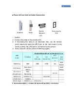
Plug in the power only after all cables are connected. While the
unit is plugged in, do not disconnect the cables or connect them
to other cables.
④
The product can be used more effectively if it is installed at a
convenient height and location. The recommended height for a
normal adult is 150cm from the ground to the center of the
terminal.
⑤
Input power for the system is AC 100~240V, 50/60Hz.
Note
If the power unit is not grounded, static electricity, etc may cause
problems.
Summary of Contents for Fingkey Access +
Page 1: ......
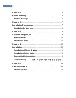
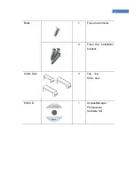
Page 4: ...4 Chapter 1 Before Installing Product Package...
Page 7: ...7 Chapter 2 Installation Environment...
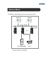
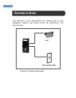
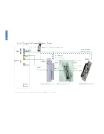
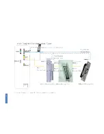
Page 9: ...Chapter 3 System Configuration Network Mode Standalone Mode...
Page 18: ...18...
Page 19: ...19...
Page 22: ...22 Chapter 5 After Installation After Installation...


