Nitek EtherStretch ER8500C Installation And Operation Manual Download Page 8

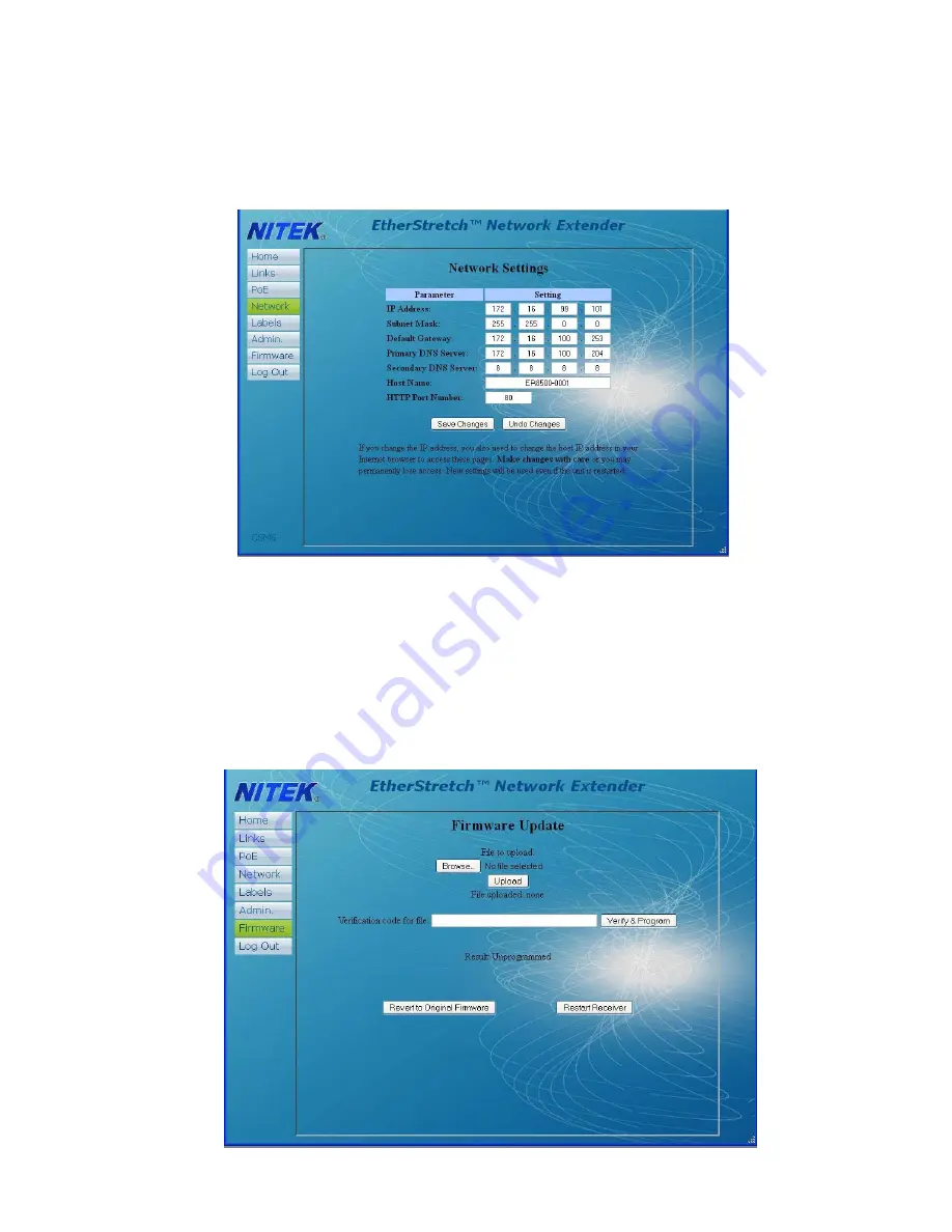
Next would be setting up the network connection. Select the 

Network

 button. From within the network page you can 

change the IP address of the unit and the subnet mask along with other settings. Remember once you change the net-
work address you will have to login again to the unit. If you have multiple units in one installation you will need a 
unique IP address and host name for each unit. It will operate with a single host name but can cause confusion for a 
network administrator. The IP address allows you to access the web interface.  

Units are shipped from the factory with the most up to date firmware. Firmware is from time to time updated to add fea-
tures to the unit. These updates are mostly in the form of added features in this webpage section. Firmware updates 
will be posted to the Nitek website at www.nitek.net and can be found under the support tab. In the home screen page 
you can see what firmware version is loaded in you unit and when it was loaded. To update the firmware, down load 
update to your PC. From the Firmware Update page browse to the update file location on your PC and click the 
“Upload” button. Next, enter the verification code and select the “Verify and Program” button. When complete the Re-
sult will change to “programmed”. You will need to reset the unit in order the have the code take effect. Reverting to 
Factory Installed Firmware will keep all user settings but will change to the original firmware.  

Summary of Contents for EtherStretch ER8500C

Page 1: ...any heat sources such as radiators heat registers stoves or other appara tus that produce heat Patent Pending USA and Europe Euro Pat App 2779641 NITEK De Aar 99 8253 PN Dronten The Netherlands Tel 31...

Page 2: ...E the ambient temperature in a closed or multi unit rack assembly could greatly exceed the ambi ent temperature outside that assembly b Air Flow Leave space on the sides of the unit for airflow into t...

Page 3: ...flashing slowly it will indicate that the network has a loop in it and data is cascading It is recommended to remove the second LAN jack if this occurs and see if the problem goes away The data speed...

Page 4: ...n on followed by the LINK STATUS LED on the Network Port The IP camera or other Ethernet device should now be ready to operate Continue installing the remaining transmitters as needed Connector LED OF...

Page 5: ...e maximum power available for your length of coax 11 If the needed level of power is not available for the length of coaxial cable alternate options are available One method is to directly power the t...

Page 6: ...ort of the ER8500 ER16500 unit Go into the network setting for your PC and set its address to 192 168 1 100 and a subnet mask of 255 255 255 0 The default IP address of the ER unit is 192 168 1 1 ente...

Page 7: ...onal rights Restricted will only allow this person to see the Home screen and the Log Out Screen POE On Off will allow a user to turn off power to individual transmitters and cameras and to make syste...

Page 8: ...is from time to time updated to add fea tures to the unit These updates are mostly in the form of added features in this webpage section Firmware updates will be posted to the Nitek website at www ni...

Page 9: ...perly setup This can lead to a false reading In this rare case Mode may need to be set to DM Discovery Mode to allow for cameras to be configured Once the cameras are properly configured the setting c...

Page 10: ...each port at the ER8500C ER16500C end In this screen you can also turn on all of the POE ports or reset the whole unit is needed The Labels button takes you the screen where you can apply a custom la...

Reviews: