1
Installation and Operation Manual
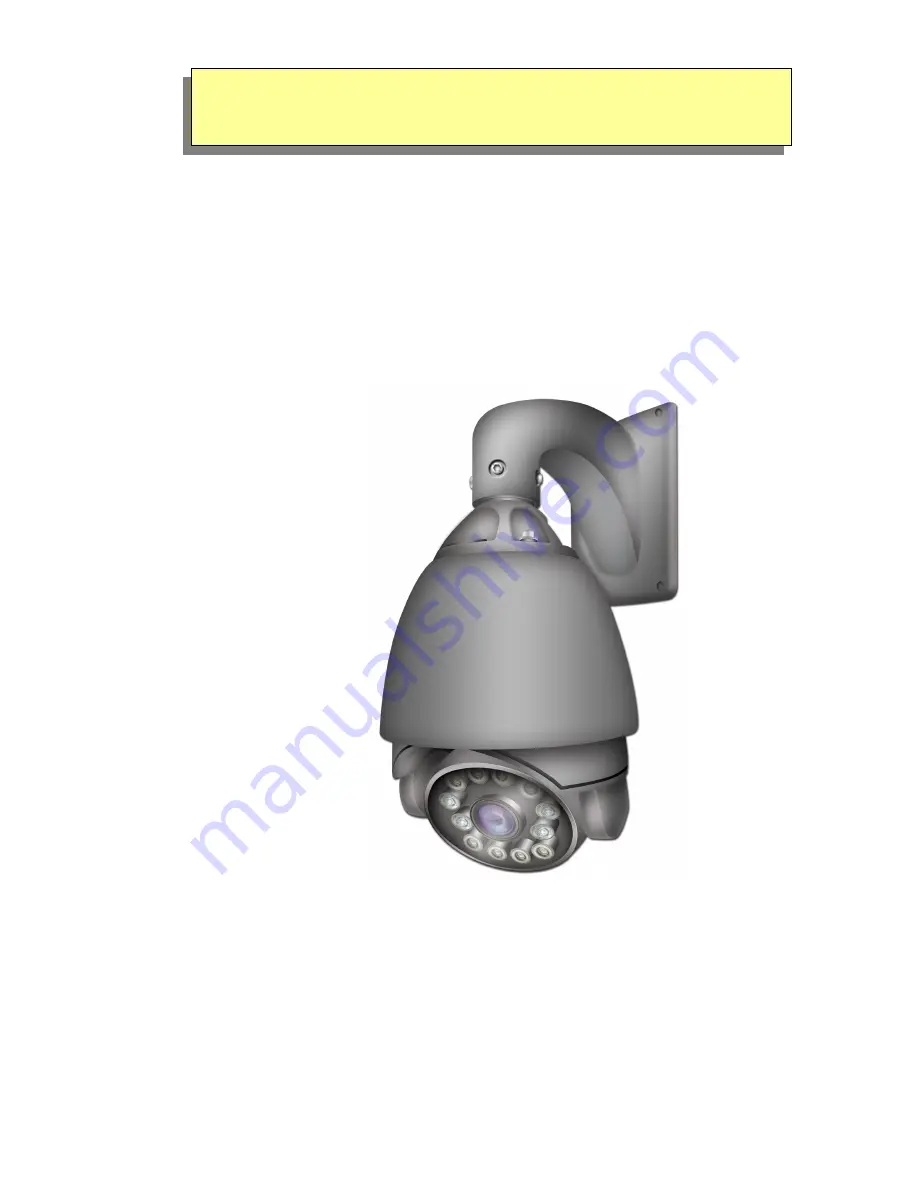
PTZ630 HIGH Speed Pan Tilt Zoom
24V AC model with Intelligent IRs
Models CoveredPTZ630K 27 x ZoomPTZ630P 36 x Zoom
Version 2.0
Last Revised: 14/12/2012
PTZ Dome + Intelligent IRs
Page 1: ...llation and Operation Manual PTZ630 HIGH Speed Pan Tilt Zoom 24V AC model with Intelligent IRs Models Covered PTZ630K 27 x Zoom PTZ630P 36 x Zoom Version 2 0 Last Revised 14 12 2012 PTZ Dome Intellige...
Page 2: ...re than one PTZ on a site 18 Setting up a unique Address and Baud Rate in the PTZ630 18 Setting the Baud Rate 19 Using the PTZ630 keypad with the PTZ630 20 Presets and other functions 21 Presets How t...
Page 3: ...luorescent lights Using an anti surge protection device is recommended to prevent damage to the PTZ630 from lightning and mains surges Damage to units by lightning or mains voltage surges is not cover...
Page 4: ...0 can set up to 220 presets each preset containing the lens zoom and angle positions b You can set up to 8 tours Patrol Tracks each with up to 32 presets c Can record in Mode Scan up to 4 patterns wit...
Page 5: ...ctive cover Controlling the PTZ630 In order to access the PTZ630 menu via keyboard or Alien DVR call preset 95 To move up and down the menu use the up or down direction keyor joystick controller Move...
Page 6: ...o first preset position Press Preset Preset Number then Enter A Setting Preset xxx will then be displayed Repeat this for each preset set To start the patrol tour select Shot Call Tour Number 65 68 pa...
Page 7: ...e comfort of your own premises Overview introduction to fitting PTZ equipment Generally speaking PTZs require four things 1 They require a power supply and a cable to supply this power to the PTZ The...
Page 8: ...ase note DVR s tend to require very good video signals to function correctly and passive baluns can loose some signal strength over the 50 metre mark so try to restrict the use of passive baluns to be...
Page 9: ...Characteristics of RS485 As specified by RS485 standards RS485 is a half duplex data transmission type with characteristic impedance of 120 The maximum load capacity is 32 units PTZs keyboards and DVR...
Page 10: ...better reliability so the PTZs function as expected A common mistake installers make is not making sure the 120 resistor is fitted on the LAST PTZ Also installers often set the termination in another...
Page 11: ...e not fitted in these PTZ cameras so you will need to fit one across the RS485 connections on the relevant domes As the star configuration is not in conformity with the requirements of RS485 standards...
Page 12: ...hough the RS485 distributor is a small additional expense it takes some of the guess work out of the installation design and gives a more flexible approach to cabling which itself can save time and mo...
Page 13: ...a good idea what your options are Below is a general schematic diagram showing you some of these options BALUN PTZ 24V AC LOCAL PSU 240V CAT 5 CAT5 Carries Video Control Data CCT CAMERA Video Power T...
Page 14: ...re detail on how to connect the RS485 data Please also read the RS485 WIRING METHODS TIPS section towards the beginning of these instructions If the voltage of the PTZ drops below around 20V A C it wi...
Page 15: ...and the dome will function erratically You must always use a core from a PAIR not two cores from two different pairs Connecting the video out of the PTZ The PTZ630 has a short BNC lead attached to it...
Page 16: ...available In the DVR with Pelco D set you must make sure you set up the baud rate to 2400 If you want to connect more than one keypad to the PTZ or use a keypad and DVR then you can do this by includ...
Page 17: ...17 24V AC INPUT RS485 A ORANGE RS485 B YELLOW RS485 INPUT ON DVR RG59 Video Cable Power Cable 24 VAC RS485 COMBINE R RS485 Data Cable RS485 Data Cable...
Page 18: ...ens The first 8 switches are used for the address and dipswitches 9 and 10 are used for the baud rate Note that the protocol is detected automatically Setting Address To set the PTZ address at 1 put s...
Page 19: ...16 OFF OFF OFF OFF ON OFF OFF OFF 17 ON OFF OFF OFF ON OFF OFF OFF 18 OFF ON OFF OFF ON OFF OFF OFF 255 ON ON ON ON ON ON ON ON Table 1 One keyboard can therefore control up to 255 x PTZ630 cameras Se...
Page 20: ...nded to use a POW802 for this purpose Now press the keypad ON button Select a PTZ camera by pressing CAM button followed by camera address and Enter The LCD display will indicate the camera channel se...
Page 21: ...e keypad PRESET xx Enter where xx is the preset number you wish to store For example PRESET 01 Enter would store PRESET 01 and the camera would always go to this location when 01 is CALLED Note that s...
Page 22: ...t You can set up to 220 presets but to run a patrol you have to enter the menu and select a patrol number and then allocate the presets that you require So if you need to change an existing preset jus...
Page 23: ...utton again to select the white circle and using the joystick right direction move to the Speed parameter Use the same method to set the Speed and Time Note that the maximum number of presets that can...
Page 24: ...To setup the Auto Scan you need to move to the start position and enter CALL 221 Enter or SHOT 221 Enter on the keypad Alternatively dependent on PTZ firmware installed in PTZ630 you can enter CALL 9...
Page 25: ...of standard pan and tilt movements or lens commands The maximum time of the recording is related to the number of actions recorded but the recording should last for at least a 120 second interval A r...
Page 26: ...eypad You will see the Main Menu displayed on the screen Using the joystick up down direction movement select the SYSTEM SETTING menu Press the OPEN button or IRIS button to enter menu and move down t...
Page 27: ...t and SHOT 0 ENTER or OPEN or IRIS to close 65 Call Patrol 1 221 Set AB Scan point A 66 Call Patrol 2 222 Set AB Scan point B 67 Call Patrol 3 223 Call AB Scan at High Speed 68 Call Patrol 4 224 Call...
Page 28: ...w the main menu option selected on the left hand side of the page and a breakdown of that menu page on the right hand side of the page MAIN MENU To enter the main menu system press CALL 95 Enter or SH...
Page 29: ...bers are in binary format so ID number value Dipswitch Number 1 2 3 4 5 6 7 8 Value 1 2 4 8 16 32 64 128 So for example to set ID number 3 switch 1 2 ON ID number 7 switch 1 2 3 ON Soft Address If you...
Page 30: ...r Camera menu Screen Tips ON OFF Switch ON to open the display tips for the Zoom function Auto ICR ON OFF Switch to ON to enable IR operation NOTE If this is set to OFF IR light will be blocked This o...
Page 31: ...g digital zoom the digital zoom speed increases or decreases according to the zoom distance Park Action Time 5 secs 255 secs OFF This enables the PTZ to stay at the Park Action selected for a stipulat...
Page 32: ...to the preset number selected Edit Allows adjustment for direction and lens zoom Remove Delete a preset number Exit Limit Stop OFF ON Set a limit parameter to stop movement outside the selected frame...
Page 33: ...rameter is the number of seconds that the PTZ will stay at the preset position and that can be from 0 240 seconds Preview 1 8 patrol track tour number Preview the tour number selected Invalid Patrol T...
Page 34: ...fault FOLLOW ALWAYS 1 240 seconds Sets the alarm trigger time Channel 1 3 Select the alarm channel 1 2 or 3 Input NC NO Set alarm for normally closed or normally open connection Enable OFF ON Switch t...
Page 35: ...he value to 0 will switch off the IRs If the value is increased then the higher the setting the lighter it has to be in order to switch off the IRs The default setting is 170 Brightness Low Power Unif...
Page 36: ...em Installation PTZ630 Dimensions Wall Bracket Dimensions 1 Mark bracket positioning 2 Drill holes Remove wall bracket from packaging and mark holes for securing bracket base Drill holes for mounting...
Page 37: ...rew the dipswitch plastic cover to get access the the bank of dipswitches that can be setup to change the ID number and transmission baud rate Refer to the earlier section for details on settings The...
Page 38: ...emoved To ensure that the camera is waterproof install the rubber seals on the wall mount bracket and take the cable out from the wiring hole as shown Then fit dome to wall using 4 screws Ensure that...
Page 39: ...ch is detected by the dome This allows the dome to immediately action the selected operation in an alarm condition To set these special operations you need to enter the Alarm menu Channel 1 3 Select t...
Page 40: ...Time in order to return from alarm action to original function but you have to add the Park Action Time to the Stay time before the Park Action is implemented Entering the Camera Module Menu Dependan...
Page 41: ...ess Weatherproof Rating IP66 Lightning Protection TVS3000V lightning protection Dimensions 300 x 300 x 450mm Weight without bracket 4 o Kg without bracket All specifications are approximate nitedevil...