Nipon Coolair MB12 GA Installation And User Manual Download Page 7

3

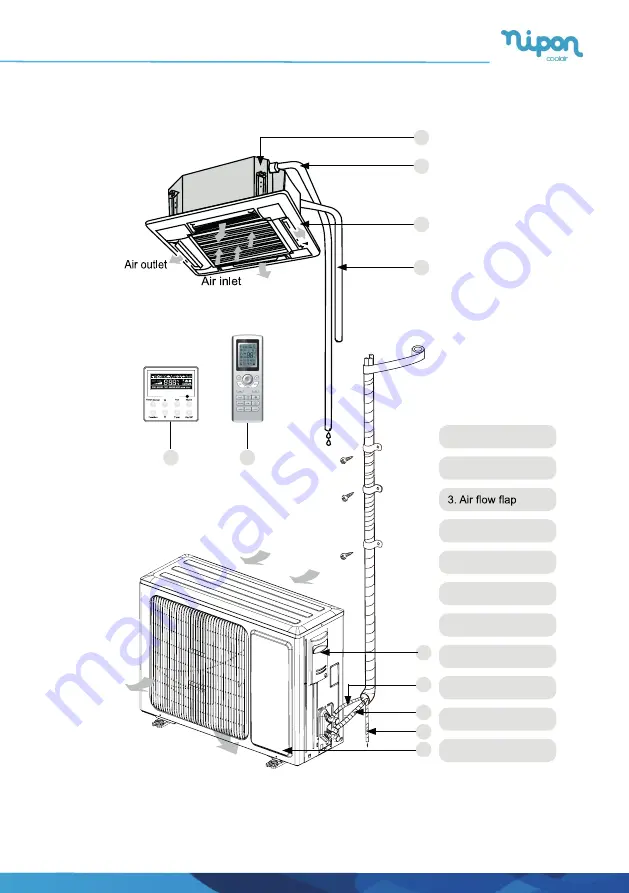
2 Outline of the Unit and Main Parts

1. Drainage device

2. Drainage pipe

4. Connection pipe

5. Wired Controller 

6. Wireless Controller

7. Big handle

8. Liquid Pipe

9. Gas pipe

10. Drainage pipe

11. Front Board

Indoor

Outdoor


2

3

4

7

5

6

1

8

9

10
11

Air inlet

Air outlet

Fig.1

Cassete - Multi-Split

Summary of Contents for MB12 GA

Page 1: ...Thank you for choosing our product For proper operation please read this manual carefully and keep this manual If you lose the user manual contact the installer or visit www nipon coolair com or send...

Page 2: ...the environment or human health from un controlled waste disposal recycle it responsibly to promote the sustainable reuse of mate rial resources To return your used device please use the return and co...

Page 3: ...uction for icons on display screen 4 3 3 Introduction for buttons on remote controller 5 3 4 Function introduction for combination buttons 9 5 Installation of the Unit 14 5 1 Installation of the Indoo...

Page 4: ...ied personnel may be dangerous The appliance shall be stored in a room without continuously operating ignition sources for example open flames an operating gas appliance or an operating electric heate...

Page 5: ...an extension cord Do not put other loads on the power supply use a dedicated power circuit 8 Firmly clamp the interconnecting wires so their terminals receive no external stresses Incomplete 9 After c...

Page 6: ...ge unless they have been given supervision or instruction concerning use of the appliance by a person responsible for their safety 18 Children should be supervised to ensure that they do not play with...

Page 7: ...inage device 2 Drainage pipe 4 Connection pipe 5 Wired Controller 6 Wireless Controller 7 Big handle 8 Liquid Pipe 9 Gas pipe 10 Drainage pipe 11 Front Board Indoor Outdoor 2 3 4 7 5 6 1 8 9 10 11 Air...

Page 8: ...d signal Turbo mode X fan mode Set temperature Set time TIMER ON TIMER OFF Child lock Up down swing Set fan speed AIR function I feel Light Temp display type Set temp Outdoor ambient temp Indoor ambie...

Page 9: ...F F F Note Note 1 2 T F RY T Cassete Multi Split...

Page 10: ...set Do not put the remote controller near the object of high temperature or low temperature in order to avoid detecting inaccurate ambient temperature Press this button to set HEALTH function ON or O...

Page 11: ...r timer on After pressing this button icon disappears and the word ON on remote controller blinks Press or button to adjust TIMER ON setting After each pressing or button TIMER ON setting will increas...

Page 12: ...he constant circulating valid After that air conditioner will be turned on or turned off according to setting time ON OFF button has no effect on setting If you don t need this function please use rem...

Page 13: ...off display light on indoor unit icon on remote controller disappears Press this button again to turn on display light icon is displayed SLEEP button LIGHT button 14 15 r temperature indicator on ind...

Page 14: ...of battery box along the arrow direction 2 Replace two 7 AAA 1 5V dry batteries and make sure the position of polar and polar are correct 3 Reinstall the cover of battery box signal sender battery Co...

Page 15: ...sket from falling off 6 Wireless Controller Battery 1 2 To control the indoor unit 7 sealing plaster 1 8 Fastener 4 To fasten the sponge 9 Insulation 1 To insulate the gas pipe 10 Insulation 1 To insu...

Page 16: ...ake sure that there are enough space for care and maintenance and the height fall between the indoor unit and ground is above 1800mm 7 When installing the suspension bolt check if the installation pla...

Page 17: ...cooling and heating effect performs 4 4 Electrical Requirement Electric Wire Size and Fuse Capacity Table 4 Indoor Units Power Supply Fuse Capacity Min Power Supply Cord V Ph Hz A mm2 12 24k 220 240V...

Page 18: ...stallation of the Indoor Unit 1 1 Indoor unit dimension For the units 12 18k For the units 24k Fig Table Item Model A B C D E F G MB 12 GA 670 666 600 496 145 240 596 MB 18 GA MB 24 GA 950 840 780 680...

Page 19: ...he water pump and the 5 Remove the gasket anchor board and tighten the nut remained 6 Remove the paper template 1 3 Installing the Suspension Bolts 1 Using the installation template drill holes for bo...

Page 20: ...t is horizontal as shown below Horizontal tester Fig 8 Fig 9 2 Installation of the Connection Pipe 2 1 Flare Processing 1 Cut the connection pipe with the pipe cutter and remove the burrs 2 Hold the p...

Page 21: ...and secure it with tape Fig 11 Pipe Cutter Cutt line Heat insulating pipe CAUTION To prevent breaking of the pipe avoid sharp bends Bend the pipe with a radius of curvature of 150 mm or over If the p...

Page 22: ...pe to see if it leaks then take the treatment of heat insulation as shown in the Fig 12 Use the medium sized sponge to insulate the coupler of the gas pipe Fig 12 Table Flare nut tightening torque Pip...

Page 23: ...ulation on the Pipe Joints Indoor Side Only Stick coupler heat insulation large and small to the place where connecting pipes Fig 14 2 7 Liquid Pipe and Drain Pipe If the outdoor unit is installed low...

Page 24: ...in case of refrigerant leak 3 Connect the hose used for evacuation to the vacuum pump 4 Open the switch at the lower pressure side of the manifold valve assembly and start the vacuum pump Meanwhile th...

Page 25: ...the manifold valve assembly to two service ports to quicken the evacuating speed 7 Slightly open the liquid valve and let some refrigerant go to the connection pipe to balance the pressure inside and...

Page 26: ...ain hose Insulating tape accessory Fig 19 5 4 2 Installing the Drain Pipes 1 Insert the drain pipe to the drain outlet of the unit and then tighten the clamp securely with tape 2 Connect the extension...

Page 27: ...inage side of each indoor unit Fig 21 6 Install one water trap for each unit 7 Installation of water trap shall consider easy cleaning in the future Fig 21 Fig 22 Fig 23 8 Connection of drainage branc...

Page 28: ...he drain hose to the drain lift pipe and insulate them 2 Connect the drain hose to the drain outlet on the indoor unit and tighten it with the clamp Drain lift pipe Fig 27 4 Secure a downward gradient...

Page 29: ...ter pot The length of the pipe should be about 100mm Above 100mm Drain vent for repair use plastic stopper is included drain the water in waterspoit by this outlet vent Fig 5 The Panel Installation 5...

Page 30: ...3 4 Fig 3 5 2 Installing the Panel 1 2 Latch other two hooks 3 Tighten four hexagonal screws under the latches about 15mm 4 Adjust the panel along the direction indicated by the arrow as shown in Fig...

Page 31: ...rcuit and install a special receptacle to supply power to the air conditioner The special branch circuit breaker is installed in the permanent wiring Always use a circuit that can trip all the poles o...

Page 32: ...bend the solid wire to form a loop suitable for the terminal screw 4 Shape the loop wire properly place it on the terminal board and tighten securely with the terminal screw using a screwdriver 2 For...

Page 33: ...d colors with those of the indoor unit side Erroneous wiring may cause burning of the electric parts Always fasten the outside covering of the connection cord with cord clamps If the insulator is not...

Page 34: ...Electric wiring of indoor unit side Remove the electric box cover from the electric box sub assy and then connect the wire Power supply terminal board Seal here to avoid leakage Fig 3 Cassete Multi S...

Page 35: ...d on the corresponding marks as shown in Fig 3 Ground both the indoor and outdoor units by attaching a ground wire Unit shall be grounded in compliance with the applicable local and national codes 6 I...

Page 36: ...erature sensor is open short circuited 12 F3 Outdoor ambient temperature sensor is open short circuited 13 F4 Outdoor condenser temperature sensor is open short circuited Outdoor discharge temperature...

Page 37: ...e controller the dual 8 nixie tube set under on status displays indoor temperature for 3s and then resume to display the set temperature If there is error error code will be displayed If there s multi...

Page 38: ...ource or too many people inside the room The door or window is open There is obstacle at the air intake or outlet The set temperature is too high There is refrigerant leakage The performance of room t...

Page 39: ...s installed in a room where the air is extremely 1 Open the air inlet grille 1 How to open the panel grille of the 24k cassette type unit Push the buckle as shown in the Release the screws under buckl...

Page 40: ...t and remove the grille Filter screen Filtering element Support Bolt up wash it by warm water meld with the Note Never use hot water over 45 C in case of color fading or turning yellow The same as ste...

Page 41: ...is well ventilated The continuous ventilation status should be kept during the operation process Check whether there is fire source or potential fire source in the maintenance area The naked flame is...

Page 42: ...ling appliances specialized for R32 Make sure that different kinds of refrigerant won t contaminate with each other After filling is finished please do the leakage detection before test running anothe...

Page 43: ......

Page 44: ......

Reviews: