background image


Nilfisk ALTO 


Operator's Manual - 

SCRUBTEC 770 / 784 / 795

SCRUBTEC 770 / 784 / 795

SCRUBTEC 770 / 784 / 795

SCRUBTEC 770 / 784 / 795

SCRUBTEC 770 / 784 / 795

                                                                         - 31 -

Section II

Parts and Service Manual

(70935A)

U.S. Patent No. 6,760,947; No. 6,105,192; No. RE39, 581 (Deluxe Machines)

SCRUBTEC 770 S
SCRUBTEC 770 L
SCRUBTEC 784 S
SCRUBTEC 784 L
SCRUBTEC 795 S
SCRUBTEC 795 L

Summary of Contents for Scrubtec 770 L

Page 1: ...nted in the U S A SCRUBTEC 770 S SCRUBTEC 770 L SCRUBTEC 784 S SCRUBTEC 784 L SCRUBTEC 795 S SCRUBTEC 795 L U S Patent No 6 760 947 No 6 105 192 No RE39 581 Deluxe Machines Operator s Manual READ THIS MANUAL English 2 30 Parts List 31 67 EN ...

Page 2: ...bly L Models 38 Parts List 39 Control Panel Assembly 40 Parts List 41 Squeegee Swing Arm Assembly 42 Parts List 43 Squeegee Swing Arm Assembly 44 Parts List 45 Traverse System Assembly 46 Parts List 47 Brush Head Assembly 48 Parts List 49 Brush Motor 50 Gearbox 51 Imperial Transaxle Parts 52 Control Panel Connection Diagram S Models 54 Front of Machine Connection Diagram S Models 54 Control Panel ...

Page 3: ...apors Do not use this machine with or near fuels grain dust solvents thinners or other flammable materials This machine is not suitable for picking up hazardous dust DANGER Lead acid batteries generate gases which can cause an explosion Keep sparks and flames away from batteries Do not smoke around the machine Charge the batteries only in an area with good ventilation Make sure that you unplug the...

Page 4: ...terials used with this type of machine can leave wet areas on the floor surface These areas can cause a dangerous condition for the operator or other persons Always put Caution signs around near the area you are cleaning WARNING Improper discharge of waste water may damage the environment and be illegal The United States Environmental Protection Agency has established certain regulations regarding...

Page 5: ... 5 1 5 cm overlap Brush Speed 200 rpm 200 rpm 200 rpm Brush Pressure Variable 150 lbs 220 lbs Variable 150 lbs 220 lbs Variable 150 lbs 220 lbs Speed Forward Variable to 230 ft min Variable to 230 ft min Variable to 230 ft min Speed Reverse Variable to 180 ft min Variable to 180 ft min Variable to 180 ft min Charger 36V 21A 115V 60hz 36V 21A 115V 60hz 36V 21A 115V 60hz Length 68 28 inches 173 cm 6...

Page 6: ...sh Speed 200 rpm 200 rpm 200 rpm Brush Pressure Variable 140 lbs 220 lbs Variable 140 lbs 220 lbs Variable 140 lbs 220 lbs Speed Forward Variable to 230 ft min Variable to 230 ft min Variable to 230 ft min Speed Reverse Variable to 180 ft min Variable to 180 ft min Variable to 180 ft min Charger 36V 21A 115V 60hz 36V 21A 115V 60hz 36V 21A 115V 60hz Length 68 28 inches 173 cm 67 inches 170 cm 65 0 ...

Page 7: ...hine to the top of the ramp 10 Turn the key switch OFF 11 Fasten the machine to the vehicle How To Remove The Machine From A Van Or Truck 1 Make sure there are no obstructions in the area 2 Make sure the unloading ramp is at least 2 4m long and strong enough to support the machine 3 Make sure the ramp is clean and dry 4 Put the ramp in position 5 Unfastenthemachine WARNING The machine is heavy Mak...

Page 8: ...Switch Power BrushUp Down Charge Indicator One Touch Switch SYMBOLS USED ON SCRUBTEC 770 784 795 Hazard Alert Symbol On Off Key Switch BrushUp Down Solution Control AdditionalBrush Pressure Charge Battery Meter SYMBOLS USED ON SCRUBTEC 770 S 784 S 795 S SCRUBTEC 770 L 784 L 795 L Traverse Speed Control SYMBOLS USED ON SCRUBTEC 770 S 784 S 795 S SYMBOLS USED ON SCRUBTEC 770 L 784 L 795 L ...

Page 9: ... leave machine on a ramp or dock WARNING READOPERATOR S MANUALBEFORE OPERATINGTHIS MACHINE EXPLOSIVEGASES CANCAUSESEVERE INJURY DEATH ORDAMAGE TRANSFORMER Keep flammable materials away from batteries Charge in a cool well ventilated area BATTERIES CONTAINSULFURIC ACID CANCAUSE SEVEREINJURY Avoid contact with skin eyes or clothing If contact flush with water Get medical attention If internal contac...

Page 10: ...osition for normal scrub Solution Control Knob See Figure 1 Item E The solution control knob regulates the flow of cleaning solution to the floor To increase the flow turn the knob clockwise To decrease the flow turn the knob counter clockwise Forward Switch See Figure 1 Item F The forward switch turns the traverse motor on and if the brush motors are in the down position it also activates the bru...

Page 11: ... Operator s Manual SCRUBTEC 770 784 795 SCRUBTEC 770 784 795 SCRUBTEC 770 784 795 SCRUBTEC 770 784 795 SCRUBTEC 770 784 795 11 Figure 1 MACHINE CONTROL PANEL SRUBTEC 770 S 784 S 795 S F G B F A H I J K L M N E C D ...

Page 12: ...on until the brush head travel stops or desired position is reached Solution Flow Control See Figure 2 Item E The solution flow switch regulates the flow of chemical solution to the floor To increase the flow push the solution flow switch in the down position until desired flow is reached To decrease the flow push the solution flow switch in the up position until the desired flow is reached To shu...

Page 13: ...rs See Figure 2 Item K L M The circuit breaker reset buttons are located on the control panel The breakers are located as follows Item L and M Brush Motors 35A Item N Key Switch 5A If a circuit breaker trips determine which motor is not operating and turn the key switch OFF Wait five minutes and push the reset button back in Turn the key switch ON and try again An authorized service person should ...

Page 14: ...g currentsettings Screens Available to Operator Battery blinks when low voltage occurs Water droplets off when solution is off and they are flashing when solution is on Arrows indicating vacuum status They are flashing when vac is on and off when vac is off SCREEN1 SCREEN2 Example SCREEN3 Diagnostic The Diagnostic only It will not show unless a fault with the machine occurs When the fault happens ...

Page 15: ...ey switch off or disconnect the power to the battery to apply the brake There is a mechanical lever located on the brake This lever is an override To manually release the brake rotate the lever toward the rear of machine counter clockwise To return the brake to normal or to apply the brake rotate the lever towards the front of the machine clockwise NOTE If the lever is left in the override positio...

Page 16: ...tank support bracket 5 Removetherecoverytank 6 Place the batteries in the solution tank as shown in figures 6a and 6b WARNING Lifting batteries without help could result in an injury Get help to lift the batteries The batteries are heavy WARNING Working with batteries can be dangerous Always wear eye protection and protective clothing when working near batteries NOSMOKING 7 Connect the battery cab...

Page 17: ... a result theelectrolytecouldoverflow fromthecells Alwaystopoff the cells with distilled water after charging CAUTION Irreversible damage will occur to the batteries if the electrolyte level doesnotcovertheplates Keepthe electrolyte at the correct level CAUTION Machine damage and discharge across the tops of the batteries can occur if the batteries are filled above the bottom of the tube in each c...

Page 18: ...sides are at least two inches away from walls and other objects Make sure there are no objects near the vents on the bottom of the charger 4 Disconnect the battery pack connector from the batteries 5 Connect the DC connector on the charger to the battery pack connector See figure 8A 6 Connect the battery charger AC cord located at the rear of the machine to a 10 amp min 230V properly grounded wall...

Page 19: ...nd remove them See figure 9 6 Putabrushorpaddriverunderthebrushmotorplate See figure 10 7 Alignthelugsonthemotorgimbalwiththeslotsinthe brushgimbal 8 Pull the brush up until the gimbal locks 9 Repeat steps 6 7 and 8 to install the second brush orpaddriver How To Remove The Brushes Or Pad Drivers To remove the brushes or pad drivers from the machine followthisprocedure 1 Turn the key switch ON 2 Pu...

Page 20: ... this be done while traversing If you stop and do it some solution can be left on the floor Reprogramming One Touch If you do not want to use the factory default settings you may reprogram the setting by following the procedures below 1 Place the machine in the desired scrub condition by using the one touch and individual switches 2 Press and hold the green one touch button until you see the LCD d...

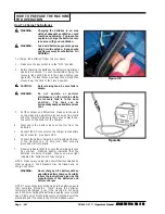
Page 21: ... drain hose at the rear of the machine To fill the solution tank follow this procedure 1 Remove the solution tank lid See figure 15 2 Fill the solution tank with water 3 Add a cleaning chemical to the water for the correct amount follow the directions shown on the container WARNING Water solutions or cleaning materials used with this type of machine can leave wet areas on the floor surface These a...

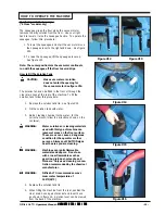
Page 22: ...r cleaning materi als used with this type of machine can leave wet areas on the floor surfaces These areas can cause a dangerousconditionfortheoperator or other persons Always put CAU TION signs near the area you are cleaning To clean a floor follow this procedure 1 Put the water and a cleaning chemical in the clean solution tank 2 Turn the key switch ON If one touch feature is used press the gree...

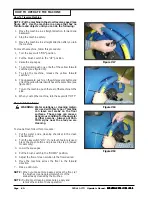
Page 23: ...intenanceProceduresMustBeDoneEveryDay Keep the machine clean it will need fewer repairs and havelongerlife Do These Procedures When You Begin Your Work Period 1 Turn off key switch 2 UnplugchargerfromACoutletandwrapcordaround bracket at rear of machine 3 Makesuretherecoverytanklidisoncorrectly see figure 20 4 MakesuretheScreenfilteroverthevacuummotor is clean and in position see figure 20 5 Make s...

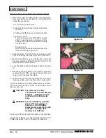
Page 24: ...n use a high pressurewaterhosetoflushthetankorhose Putthe water hose into the drain hose 4 Leavethetanksandthedrainvalvesopentodryinthe air 5 Check the squeegee blade Use a cloth to clean the squeegee blade If the squeegee blade is damaged or worn turn or replace the blade 6 Check and clean the recovery lid gasket Use a mild cleaning solution and rinse the parts in clean water Check the batteries ...

Page 25: ... of the batteries Do not add acid to battery after installa tion NOTE Alwaysturnoffkeyswitchbeforeservicingthe machine WARNING Always wear eye protection and protective clothing when working near batteries NO SMOKING 1 To inspect batteries tip up recovery tank until it locks in up position See Figure 24 2 Disconnect the batteries Use a cloth and a solution ofammoniaorbicarbonateofsodatowipethetopo...

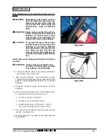
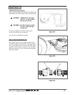
Page 26: ...followingadjustmentsaresetatthefactory however they may require slight adjustment Adjusting Squeegee Pressure To adjust the pressure refer to Figure 27 Proper adjustment will produce a uniform flare along the rear blade when the machine is moved forward To increase pressure tighten the nuts on each side of the swing arm To decrease the pressure loosen the nuts on each side Adjusting Squeegee Tilt ...

Page 27: ...el only WARNING Electrical repairs must be done by authorized per sonnel only Consult your Nilfisk ALTO Authorized Service Person to do the service procedures Use only genuine Nilfisk ALTO parts How to Clean the Solution Line If the solution line becomes clogged pull the filter assembly out from behind the brush housing Figure 30 Turn solution vavle off Remove the filter screen Figure 31 B and cle...

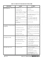
Page 28: ...n the screen filter Remove the obstruction or repair the damage Check for tripped breaker Have an authorized service person make repairs Connect the hose Turn or replace the squeegee blade Correctly install the squeegee blade Adjust the pressure of the squeegee Replace the gaskets Clean the terminals and connectors Replace the damaged cables Charge the batteries Add distilled water to each cell an...

Page 29: ...Brushes not fitted Drive system activated prior to turning key switch ON Check the traction brush and vac motor connections on the trio and check wiring from these connectors down to the traction brush and vac motors Check the brush motor connection on the trio and check the wiring from this connector down to the brush motor Check the traction motor connection on trio and wiring down to motor Exce...

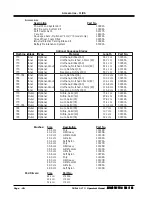
Page 30: ... Blade Type Material Length Part No 770 Inner Optional Urethane Ribbed 60 65 7 cm 30951A 770 Inner Optional Urethane Notched 1 5mm 80 65 7 cm 30955A 770 Inner Optional Urethane Ribbed 60 91 1 cm 30952A 770 Inner Optional Grout Urethane Notched1 5mm 80 91 1 cm 30957A 770 Inner Optional Gum Notched 35 91 1 cm 30716A 770 Inner Optional Neoprene Notched 80 65 7 cm 30930A 770 784 Inner Optional Gum Not...

Page 31: ...4 795 SCRUBTEC 770 784 795 SCRUBTEC 770 784 795 SCRUBTEC 770 784 795 31 Section II Parts and Service Manual 70935A U S Patent No 6 760 947 No 6 105 192 No RE39 581 Deluxe Machines SCRUBTEC 770 S SCRUBTEC 770 L SCRUBTEC 784 S SCRUBTEC 784 L SCRUBTEC 795 S SCRUBTEC 795 L ...

Page 32: ...784 795 NilfiskALTO SCRUBTEC 770 784 795 SCRUBTEC 770 784 795 SCRUBTEC 770 784 795 SCRUBTEC 770 784 795 SCRUBTEC 770 784 795 Solution Tank Assembly Drawing 11 06 1 2 3 4 5 6 7 8 9 10 11 12 13 14 15 18 17 16 19 20 45 22 23 24 21 25 26 27 21 24 21 28 29 30 31 32 31 30 33 34 35 36 37 38 39 40 41 42 43 12 44 47 46 To Electrical Panel 48 49 ...

Page 33: ...p 1 16 98465A Clamp Metal 1 17 980657 Washer Lock1 4 1 18 962139 Screw 1 4 20 x 5 8 Hex 1 19 61590A HoseHangerBracket 1 20 59614A Battery Drain Valve 1 21 53571A HoseClamp 4 22 30453A Hose 1 23 822802 Elbow 1 24 30445A SolutionHose 2 25 50358A Connector 1 26 838517 FilterScreen 1 27 830214 HoseAdapter 1 28 50359A SolutionAdapter 1 29 53568A Hinge 1 30 980614 Washer 1 4External 6 31 85395A Screw 1 ...

Page 34: ... 770 784 795 SCRUBTEC 770 784 795 NilfiskALTO SCRUBTEC 770 784 795 SCRUBTEC 770 784 795 SCRUBTEC 770 784 795 SCRUBTEC 770 784 795 SCRUBTEC 770 784 795 Recovery Tank Assembly Drawing 6 07 1 2 3 4 5 3 6 7 8 9 10 11 12 13 14 15 16 16A 17 18 11 19 20 21 22 23 9 24 20 25 26 27 28 29 30 31 20 32 33 34 35 36 38 37 39 ...

Page 35: ...d 19 1 16A 40830A Brushes Carbon 2 17 87026A Washer 1 4Flat 3 18 85728A Screw 1 4 20 x 4 Hex 3 19 43401A Housing Black 2 20 872010 Clamp 3 21 674110 Vac Exhaust Hose 1 22 962957 Screw 10 16 x 1 2 PN 2 23 52206A Chain 1 24 30620A SqueegeeAdapter 1 25 35192A SqueegeeHose 1 26 30227A DrainHousing 1 27 30226A DrainPlug 1 28 52560A O Ring 1 29 30225A DrainBody 1 30 832002 DrainValveClamp 1 31 35165A Re...

Page 36: ...O SCRUBTEC 770 S 784 S 795 S SCRUBTEC 770 S 784 S 795 S SCRUBTEC 770 S 784 S 795 S SCRUBTEC 770 S 784 S 795 S SCRUBTEC 770 S 784 S 795 S Electrical Panel Assembly Drawing 2 07 Drawing 10849E 4 6 3 7 8 51 22 11 7 12 13 5 14 5 6 15 16 5 20 17 19 31 30 21 20 23 24 25 5 18 27 28 29 32 9 18 26 33 34 35 36 5 10 37 2 38 39 50 1 47 48 49 40 10 46 45 44 41 42 43 ...

Page 37: ...16 170781 Screw Set 1 4 20 x 3 4 1 17 193951 Trim 8 1 18 83307A Stud 1 4 20 11 19 61589A ElectricalPanel 1 20 54764A Insert 1 4 20 4 21 54763A Insert 8 32 2 22 40736A MainWiringHarness Std 1 23 40125A Contactor Vacuum 1 24 41801A Contactor Brush 1 25 41802A Contactor Main 1 26 61682A Cable Upper 1 27 40735A Controller Solo 1 28 40759A TraverseHarness 1 29 80254A Screw 8 32 x 1 2 30 962666 Screw 10...

Page 38: ...70 784 795 NilfiskALTO SCRUBTEC 770 L 784 L 795 L SCRUBTEC 770 L 784 L 795 L SCRUBTEC 770 L 784 L 795 L SCRUBTEC 770 L 784 L 795 L SCRUBTEC 770 L 784 L 795 L Electrical Panel Assembly Drawing 2 07 Drawing 10855E 4 3 6 8 7 22 11 7 12 13 5 6 14 15 16 18 17 19 20 20 21 5 25 24 28 26 27 5 29 30 31 5 10 18 2 9 2 5 35 31 32 33 1 5 34 23 37 ...

Page 39: ...7275A Pulley 1 10 980614 Washer 1 4ExternalLk 2 11 920110 Nut ESNA5 16 18 4 12 53569A Spacer 4 13 80285A Screw Set 5 16 18 x 1 3 4 4 14 83302A Stud 1 4 20 2 15 854849 Insulator 2 16 170781 Screw Set 1 4 20 x 3 4 2 17 193951 Trim 8 1 18 83307A Stud 1 4 20 3 19 61589A ElectricalPanel 1 20 54764A Insert 1 4 20 2 21 54763A Insert 8 32 2 22 40742A MainWiringHarness Dlx 1 23 61680A Cable Spring 1 24 534...

Page 40: ...EC 770 784 795 NilfiskALTO SCRUBTEC 770 784 795 SCRUBTEC 770 784 795 SCRUBTEC 770 784 795 SCRUBTEC 770 784 795 SCRUBTEC 770 784 795 Control Panel Assembly Drawing 11 07 1 2 3 4 3 6 7 7 9 8 10 12 13 15 16 17 18 19 20 21 22 23 24 25 26 28 29 27 30 30 31 32 17 18 33 34 35 9 36 32 31 30 44 42 43 30 41 38 26 37 39 28 40 29 24 30 32 31 ...

Page 41: ...962330 Screw 6 32 x 3 8 Pan 4 4 17 40786K Key included w 18 1 1 18 40786A Switch Key 1 NI 40786S Spacer Key Switch 1 19 40748A Switch Green Push Button 1 20 40880A LCD Display 1 21 40758A Switch Black Push Button 1 22 40168B Switch Momentary Rocker 2 23 40747A Switch 3 Position Rocker 1 24 962957 Screw 10 16 x 1 2 4 4 25 70962A Label Control 1 26 34264A Gasket 1 1 27 61739A Panel Control L 1 28 41...

Page 42: ...795 SCRUBTEC 770 784 795 SCRUBTEC 770 784 795 SCRUBTEC 770 784 795 SCRUBTEC 770 784 795 Squeegee Swing Arm Assembly Drawing 11 07 1 2 3 4 2 6 7 50 8 6 16 9 10 15 11 12 13 14 17 18 19 20 21 22 29 31 33 27 10 30 48 47 6 28 26 6 5 25 24 23 37 49 46 43 44 45 42 41 40 38 39 37 32 35 36 53 53 53 53 16 52 51 54 NOTE 51 and 52 are on top of the bracket for the S models 55 56 57 34 ...

Page 43: ...Scrubtec 770 784 See next page for standardsqueegeeassemblies NOTE indicates a change has been made since the last publication of this manual Ref Part No Description Qty Model 35 69673A SqueegeeBase 1 770 69674A SqueegeeBase 1 784 69675A SqueegeeBase 1 795 69636A Squeegee Base 29 acc 1 770 36 80316A Screw 20 x 1 Flat SS 2 All 37 38710A Spacer 2 770 38711A Spacer 2 784 38715A Spacer 2 795 38713A Sp...

Page 44: ... 784 795 SCRUBTEC 770 784 795 SCRUBTEC 770 784 795 SCRUBTEC 770 784 795 SCRUBTEC 770 784 795 NilfiskALTO SCRUBTEC 770 784 SCRUBTEC 770 784 SCRUBTEC 770 784 SCRUBTEC 770 784 SCRUBTEC 770 784 Standard Squeegee Swing Arm Assembly Drawing 11 07 Form 10847A ...

Page 45: ...stall and secure blades with clamp 47 then retighten screw 52 This will allow for different thickness NOTE indicates a change has been made since the last publication of this manual Ref Part No Description Qty 28 81217A Nut 20 1 29 920208 Nut Hex 20 1 30 980657 Washer Lock 1 31 87625A Washer Nylon1 x x1 32 4 32 81303A Nut 28 1 33 87026A Washer 4 34 87031A Washer 3 8 Flat 1 35 962720 Screw 20 x Hex...

Page 46: ... 795 SCRUBTEC 770 784 795 SCRUBTEC 770 784 795 NilfiskALTO SCRUBTEC 770 784 795 SCRUBTEC 770 784 795 SCRUBTEC 770 784 795 SCRUBTEC 770 784 795 SCRUBTEC 770 784 795 Traverse System Assembly Drawing 2 05 12 13 31 32 30 13 21 20 15 14 3 19 28 19 9 29 30 11 16 18 8 10 27 26 25 24 23 7 6 7 23 5 4 2 1 3 ...

Page 47: ...erial 1 All see page 51 for parts 15 85730A Screw Hex 4 All 16 59969A Wheel Assembly 2 All 59955A Wheel Foam Filled opt 2 All 18 81221A Lug Nut 50 20 UNF 6 All 19 980614 Washer Star Lock 25 3 All 20 61594A Main Frame 1 All 21 65963A TransaxleMount 2 All 23 87625A Washer Nylon 1 x IDx3 32 2 All 24 80011A Screw 3 8 16 x 3 2 All 25 81207A Nut 3 8 16 2 All 26 170883 Washer Lock 3 8 2 All 27 58419A Stu...

Page 48: ...70 784 795 NilfiskALTO SCRUBTEC 770 784 795 SCRUBTEC 770 784 795 SCRUBTEC 770 784 795 SCRUBTEC 770 784 795 SCRUBTEC 770 784 795 Brush Head Assembly Drawing 2 05 1 2 3 4 5 6 7 8 9 10 11 12 14 15 16 17 18 13 19 13 20 21 22 23 17 24 25 26 27 28 29 30 31 32 33 34 35 36 37 38 39 40 41 42 43 27 44 45 46 20 47 52 48 49 50 51 49 53 54 2 1 55 ...

Page 49: ...Model 34 56941A Center Lock Asm 2 All PadDriverOnly 35 11427B Poly Brush Assembly 14 2 28 11424B Poly Brush Assembly 17 2 33 11434B Poly Brush Assembly 19 2 38 11426B Grit Brush Assembly 14 2 28 11425B Grit Brush Assembly 17 2 33 11433B Grit Brush Assembly 19 2 38 17521C PadDriverAssembly 14 2 28 17520C PadDriverAssembly 17 2 33 17524B PadDriverAssembly 19 2 38 36 962714 Screw 312 18x 75Soc 2 All ...

Page 50: ...6 50520A CommutatorBracket 1 7 56480A StrainRelief 2 8 962546 Brush Board Screw 2 9 50517A Brush Board Asm w springs brushes 1 10 448396 Brush Spring 4 11 40826A Brush Assembly 4 12 55657A Lead Assembly Positive 1 13 55656A LeadAssembly Negative 1 14 59805A Helical Washer 1 15 50515A Thru Bolt 2 16 80501A Shaft Key 1 17 54238A B E Bracket Assembly Gear Box 1 13 Seam Location 7 12 15 5 6 4 1 2 3 14...

Page 51: ...A Ring Snap 1 2 507641 Seal Oil Small 1 3 52050A CapEnd 1 4 56668A O Ring 1 5 51176A Bearing Large 1 6 58316A Shaft Gear Gearbox 1 7 902605 Bearing Small 1 8 54883A Housing 1 9 58144A Seal Oil Large 1 NI DarinaGrease 4oz 9 8 7 6 5 4 3 2 1 NilfiskALTO SCRUBTEC 770 784 795 SCRUBTEC 770 784 795 SCRUBTEC 770 784 795 SCRUBTEC 770 784 795 SCRUBTEC 770 784 795 Gear Box 54238A 2 05 ...

Page 52: ...el Flange Kit includes Flange 1 10357A Studs Key Snap Rings Shims 2 2 36508A Rubber Mount 2 3 53374A Axle Oil Seal 2 4 53375A Axle Bearing 4 5 53376A Short Axle 1 6 53377A Output Gear 1 7 53378A Input Plug 1 8 53379A Outer Pinion Bearing 1 9 53380A Pinion 1 10 53381A Inner Pinion Bearing 1 11 52663A Steel Ring Coupler 1 12 69195A Rubber Coupler 1 13 45048A Motor 1 14 51720A Brushes w Springs Set o...

Page 53: ...Nilfisk ALTO Operator s Manual SCRUBTEC 770 784 795 SCRUBTEC 770 784 795 SCRUBTEC 770 784 795 SCRUBTEC 770 784 795 SCRUBTEC 770 784 795 53 NOTES ...

Page 54: ...CRUBTEC 770 S 784 S 795 S SCRUBTEC 770 S 784 S 795 S SCRUBTEC 770 S 784 S 795 S SCRUBTEC 770 S 784 S 795 S SCRUBTEC 770 S 784 S 795 S Control Panel Connection Diagram 2 05 NilfiskALTO SCRUBTEC 770 S 784 S 795 S SCRUBTEC 770 S 784 S 795 S SCRUBTEC 770 S 784 S 795 S SCRUBTEC 770 S 784 S 795 S SCRUBTEC 770 S 784 S 795 S Front of Machine Connection Diagram 2 05 ...

Page 55: ...CRUBTEC 770 L 784 L 795 L SCRUBTEC 770 L 784 L 795 L SCRUBTEC 770 L 784 L 795 L SCRUBTEC 770 L 784 L 795 L SCRUBTEC 770 L 784 L 795 L Control Panel Connection Diagram NilfiskALTO SCRUBTEC 770 L 784 L 795 L SCRUBTEC 770 L 784 L 795 L SCRUBTEC 770 L 784 L 795 L SCRUBTEC 770 L 784 L 795 L SCRUBTEC 770 L 784 L 795 L Front of Machine Connection Diagram 2 05 ...

Page 56: ...TEC 770 784 795 SCRUBTEC 770 784 795 SCRUBTEC 770 784 795 SCRUBTEC 770 784 795 NilfiskALTO SCRUBTEC 770 S 784 S 795 S SCRUBTEC 770 S 784 S 795 S SCRUBTEC 770 S 784 S 795 S SCRUBTEC 770 S 784 S 795 S SCRUBTEC 770 S 784 S 795 S Electrical Plate Connection Diagram 9 05 ...

Page 57: ...70 784 795 SCRUBTEC 770 784 795 SCRUBTEC 770 784 795 SCRUBTEC 770 784 795 57 NilfiskALTO SCRUBTEC 770 L 784 L 795 L SCRUBTEC 770 L 784 L 795 L SCRUBTEC 770 L 784 L 795 L SCRUBTEC 770 L 784 L 795 L SCRUBTEC 770 L 784 L 795 L Electrical Plate Connection Diagram 9 05 ...

Page 58: ...BTEC 770 784 795 SCRUBTEC 770 784 795 SCRUBTEC 770 784 795 SCRUBTEC 770 784 795 NilfiskALTO SCRUBTEC 770 L 784 L 795 L SCRUBTEC 770 L 784 L 795 L SCRUBTEC 770 L 784 L 795 L SCRUBTEC 770 L 784 L 795 L SCRUBTEC 770 L 784 L 795 L Control Housing Connection Diagram 2 05 ...

Page 59: ...UBTEC 770 784 795 SCRUBTEC 770 784 795 SCRUBTEC 770 784 795 SCRUBTEC 770 784 795 59 NilfiskALTO SCRUBTEC 770 S 784 S 795 S SCRUBTEC 770 S 784 S 795 S SCRUBTEC 770 S 784 S 795 S SCRUBTEC 770 S 784 S 795 S SCRUBTEC 770 S 784 S 795 S Electrical Schematic 9 05 ...

Page 60: ...UBTEC 770 784 795 SCRUBTEC 770 784 795 SCRUBTEC 770 784 795 SCRUBTEC 770 784 795 NilfiskALTO SCRUBTEC 770 L 784 L 795 L SCRUBTEC 770 L 784 L 795 L SCRUBTEC 770 L 784 L 795 L SCRUBTEC 770 L 784 L 795 L SCRUBTEC 770 L 784 L 795 L Electrical Schematic pages 58 59 9 05 ...

Page 61: ...770 784 795 SCRUBTEC 770 784 795 SCRUBTEC 770 784 795 SCRUBTEC 770 784 795 61 NilfiskALTO SCRUBTEC 770 L 784 L 795 L SCRUBTEC 770 L 784 L 795 L SCRUBTEC 770 L 784 L 795 L SCRUBTEC 770 L 784 L 795 L SCRUBTEC 770 L 784 L 795 L Electrical Schematic pages 58 59 9 05 ...

Page 62: ...NOTES ...
Page 63: ... 45 72 18 21 00 Fax 45 72 18 21 11 E mail salg nilfisk alto dk E mail service nilfisk alto dk www nilfisk alto dk Nilfisk ALTO Food Division Division of Nilfisk Advance A S Blytækkervej 2 9000 Aalborg Denmark Tel 45 72 18 21 00 Fax 45 72 18 20 99 E mail scanio technology nilfisk alto dk www nilfisk alto com NORWAY ALTO Norge AS Bjørnerudveien 24 1266 Oslo Norway Tel 47 22 75 17 70 Fax 47 22 75 17 ...

Page 64: ...list price plus transportation costs Warranty is rendered null and void if battery is not kept filled to the proper level with DISTILLED WATER NilfiskALTO POLYDUR AUTOMATICSCRUBBERSOLUTIONANDRECOVERYTANKEIGHT YEARU S GUARANTEE Your new Nilfisk ALTO machine has polydur Solution and Recovery Tanks Polydur is a rotationally molded low density linear polyethylene that won t crack or dent and withstand...

Reviews: