Nilfisk-ALTO DELTABOOSTER Operating Instructions Manual Download Page 27

27

Original Instructions

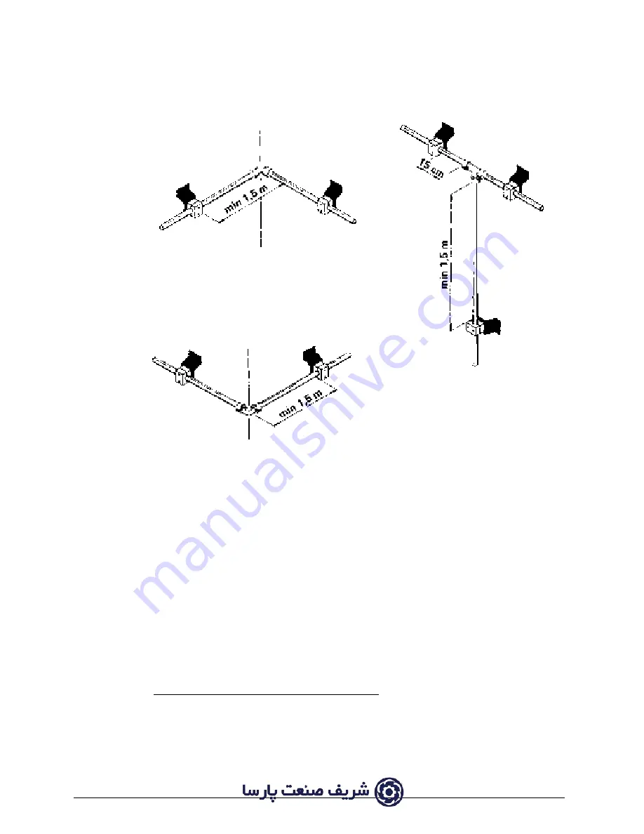
FIXATION AT CORNERS AND TEE CONNECTORS

Standard distance between pipe brackets is some 2 m.

MOUNTING OF PIPE LINES/GENERAL INSTRUCTIONS

-   Shorten the pipes by sawing off and take off burrs.
-   When bending the pipe bending radii should not be smaller than those stated in the chart 

under “U-bends/hose connections” and the bending should always be completed in a bend-
ing tool with rolling matrixes in order to prevent deformation of the pipe.

-   Union nut and cutting ring should be greased with oil and the cutting ring should be pre-fitted 

to the pipe in the screw joint or the annealed pre-mounting socket before fitting the pipe.

-   Place the pipe brackets at a maximum interval of 2 m.
-   Use 

6 hexagon-headed screw with expansion joint for wall or concrete walls when 

  mounting wall fittings, alternatively use a knock-type anchor for concrete walls, e.g. HILTI 

type HPS 8/30.

-   In systems meant for hot water, care should be taken to place the pipe brackets on a straight 

line in order to prevent the lengthwise expansion of the pipe.

Summary of Contents for DELTABOOSTER

Page 1: ...structions 7309021 d 09 2014 Operating instructions DELTABOOSTER A translation of the original instructions into Danish German French Dutch Portuguese Italian and Russian can be found on http www nilf...

Page 2: ...ypes of pipes standards 15 1 7 3 Fittings standards 16 1 7 4 Dimensioning of pipe systems pressure drop graph 21 1 7 5 Examples 23 1 7 6 Mounting requirements and hints 26 1 8 Outlet points and access...

Page 3: ...nce system 49 3 8 Operation after starting up outlet points and equipment 50 3 8 1 High pressure cock with Multipressure spray lance Outlet point A 50 3 8 2 Outlet point with foam injector and foam la...

Page 4: ...and the solution with the optimal effect on the job to be done may always be found In more technical terms the plant operates in the following way Water from a COLD and a HOT connecting valve is mixe...

Page 5: ...5 Original Instructions...

Page 6: ...ronic control that monitors the operation of the system i e a selection at any time of required pump capacity b even distribution of load on individual pumps c mixing of desired temperature of water d...

Page 7: ...solenoid valves for water inlet cold and hot water respectively various control valves temperature sensor and level switches in the float tank overflow connection of up to 6 pumps filters in in lets...

Page 8: ...e line pressure is the maximum working pressure for the individual user and is of importance to the dimensioning of the pipeline of course As a standard the system is adjusted to a line pressure of ei...

Page 9: ...sk ALTO No 3 Nozzle 4 Pump pressure 5 Max pressure 6 Water volume 7 Max temperature of inlet water 8 Voltage frequency nominal input 9 Power consumption 10 Approval 11 Serial number Production week an...

Page 10: ...ARTH 50Hz 6 7 40 5kW 6x6 7kW IP55 12 72 7 A GB AUS DELTABOOSTER 3P 415 440V 3 EARTH 6 7 20 4kW 3x6 7kW IP55 SGP U 50 60Hz USA SKB 10 7 32 7 A DELTABOOSTER 6P 415 440V 3 EARTH 6 7 40 5kW 6x6 7kW IP55 5...

Page 11: ...3 Cleaning power kW 8 8 13 2 17 6 22 0 26 4 Pressure bar 160 160 160 160 160 Water volume l min 34 51 68 85 102 Current cons A 21 41 32 11 42 81 53 51 64 21 243 363 483 603 723 Dimensions A mm 780 780...

Page 12: ...TABOOSTER is fitted with vibration absorbing rubber supports so it may be placed straight on an even surface see section 2 2 The plant must be placed in frost free premises where the maximum temperatu...

Page 13: ...the cold pipeline should be adjusted so that the water volume of each line comes as close to the required water volume as possible Water should be connected at the inlet sockets with two 1 flexible h...

Page 14: ...3phases and earth PE The minimum dimensions of the cable are determined by the power consumption of the current system cf data sheet but common to all systems is the following Max pre fuse 125 A Max c...

Page 15: ...and so that a hose length preferably of 20 m is used 1 7 2 Types of pipes standards Seamless pipes of precision steel are used for the pipe system according to DIN 2391 C of St 35 4 material quality n...

Page 16: ...nt R rsamler Verschraubung 15 X X Pipe coupling Raccord R rsamler Verschraubung 22 X X Pipe coupling Raccord R rsamler Verschraubung 30 X Pipe coupling Raccord T stykke T St ck 15 x 15 x 15 X X T Conn...

Page 17: ...ning Verschraubung 22 X X Adj Elbow coupl Raccord reg Vinkel Winkel 15 x 3 8 RG X Elbow Coude Vinkel Winkel 22 x 15 X Elbow Coude V gbeslag f r rholder Wandbeschlag 15 X X Bracket f pipe hangs Fixatio...

Page 18: ...coupling Reduction droite Ligereducering Ubergangsrohr 30 x 15 X X Straight coupling Reduction droite Ligereducering Ubergangsrohr 30 x 22 X X Straight coupling Reduction droite Sk rering Schniedring...

Page 19: ...ated Tuyau temp compenser Slange f temp kompens Schlauch Tempkomp 3 4 22 30 X X Hose temp compensated Tuyau temp compenser T tningsskive Dichtungsscheibe 3 8RG 17 mm X X Tightening washer Rondelle d e...

Page 20: ...eschlag 2 mm X Supportingfitting f tap Support Brystnippel Doppelnippel 15 x 3 8RG X X Hexagon nipple Raccord Hydroballhane Hochdruck Kugelhahn 3 8RG X X High pressure ball valve Robinet haute press H...

Page 21: ...vanized steel pipes 15x2 mm 22x2 5 mm 30x4 mm I stainless steel pipes 15x1 5 mm 22x2 mm 30x3 mm The pressure drop per metre of pipe at a given water volume may be read from the fol lowing pressure dro...

Page 22: ...22 Original Instructions...

Page 23: ...utlet points a b and c the maximum load on line b c 17 l min PRESSURE According to the diagram the use of a 50 m 15 mm DROP pipe will result in a pressure drop of 2 3 bar In the diagram you follow the...

Page 24: ...The aggregate pressure drop on the three lines is less than 15 bar and the dimension require ments have therefore been met Example 2 Branched system Selection of spray lance 2 green spray lances each...

Page 25: ...mum load on line M a1 a1 b1 50 l min If 90 m 22 mm pipe is used the resulting pressure drop will be 4 bar Total pressure drop 10 bar This means that 22 mm pipe is to be used from the pumps to outlet p...

Page 26: ...onnectors at outlet points U bends hose connections At a max temperature on the system of 75 C a compensator should be fitted at 20 m intervals if there are no elbows on the line If the pipe may expan...

Page 27: ...rder to prevent deformation of the pipe Union nut and cutting ring should be greased with oil and the cutting ring should be pre fitted to the pipe in the screw joint or the annealed pre mounting sock...

Page 28: ...of practical reasons while you are fastening the connection socket The screw spanner must have a length ap proximately 15 times as long as the width of it Lengthen it by means of a pipe if necessary P...

Page 29: ...on the high pressure hose When using the detergent trolley the high pressure hose may be fitted straight on to the outlet point A OUTLET STATION A High pressure cock To be used for connection of dete...

Page 30: ...used in conjunction with outlet station A Pressure relieved spray handle with 10 m hose Hose coil with 20 m hose Single spray lance for DELTABOOSTER plant described in section 1 9 Foam lance To be use...

Page 31: ...per 1 White 1515 1 56 27 17 19 2 0 1 2 Black 1530 2 27 27 35 41 4 2 2 3 Brown 1511 1 73 50 17 26 2 6 1 4 Green 1520 2 35 53 33 56 5 7 2 5 Blue 1508 1 80 80 17 35 3 6 1 6 Red 1513 2 27 80 27 57 5 8 1 5...

Page 32: ...on of the DELTABOOSTER The DELTABOOSTER is fitted with vibration absorbing rubber supports so it may be placed straight on an even surface The plant must be placed in frost free premises where the max...

Page 33: ...e cabinet door Fig 1 It is advisable to fix the module frame of the system to both the bulk head and bottom when mounting the system in ships The tip over safety devices 3 which are available as an ac...

Page 34: ...nnected at the inlet sockets of the system by means of two 1 flexible hose con nectors Shut off cocks should be mounted right next to the sockets on the supply lines If the water contains running sand...

Page 35: ...ed to the existing current consumption which has been stamped on the DELTABOOSTER model plate It is advisable to apply a cable with a conductor cross section of minimum 25 in preparation for a later e...

Page 36: ...I Turn the operation switch to position I The water tank will now be filled up Press the starting switch when the system has been made ready for venting of the pumps 2 5 3 Venting of pumps Venting sho...

Page 37: ...nes 2 5 5 Adjustment of line pressure Adjustment of line pressure should only be carried out by an authorized Nilfisk ALTO service technician As a standard the DELTABOOSTER is adjusted to a line press...

Page 38: ...ended for use by persons including children with reduced physical sensory or mental capabilities or lack of experience and knowledge 14 High pressure cleaners shall not be used by children or untraine...

Page 39: ...oard 2 Main switch 3 Operation switch 4 Starting button 5 Switchboard 6 Water tank 7 Motor pump units 8 Water connection 9 Oil control 10 Pressure gauge 11 Outlet socket 12 Machine feet with vibration...

Page 40: ...ressure valve overflow valve 10 Pressure switch low pressure 11 Pressure switch high pressure 12 Solenoid relief valve 13 Pressure gauge 14 Difuse filter return 15 Non return valve 16 Accumulator 17 M...

Page 41: ...evice The main switch may be locked in 0 position by means of an ordinary padlock The switch should always be locked during service checks of the system PLEASE NOTE The switchboard can only be opened...

Page 42: ...al control lamp will glow contantly cf the section on 3 10 Trouble shooting and correction The meaning of the control panel and the individual control lamps appears from Fig 2 below Fig 2 RED Flashes...

Page 43: ...ing settings and readings 1 Setting of water temperature 2 Setting of number of C3K pumps in operation 3 Reading of hour meters In all three cases the switchboard Fig 3 will have to be opened by means...

Page 44: ...5 symbol 4 is not lit ON 50 C In this position water from the two connections will be mixed to the desired mixing temperature e g 50 C The yellow indicator symbol on the control panel section 3 6 Fig...

Page 45: ...ted each module location has a specific figure connected to it The current configuration is set on the 8 poled transformer cf Fig 3 below is a setting for a configuration of 4 C3Kpumps 1 2 4 5 6 7 3 8...

Page 46: ...ons 3 5 3 Reading of hour meters On the hour meters you can read for how many hours each of the motor pump units has been running Reading as follows Motor pump unit 1 Hours 1 100 hours Example 4 hours...

Page 47: ...nd until a working pressure has been achieved Fig 4 The system is now in operation and water may be drawn off under high pressure at the individual outlets If consumption exceeds the capacity of the p...

Page 48: ...n the control panel in a given situation Fig 5 1 The water level in the water tank is low water is being 2 filled from the cold connection and 3 from the hot connection 4 Temperature adjustment is act...

Page 49: ...ay lances for 120 bar are fitted with a GREY nozzle protection and the spray lances for 160 bar are fitted with a BLACK nozzle protection The nine spray lances are marked with each their colour and on...

Page 50: ...e Operation after starting up 1 Carefully connect the high pressure hose to the quick coupling of the high pressure cock 2 Any impurities should be removed prior to coupling 2 Fit the spray lance 6 in...

Page 51: ...valve please note that maximum admixture of detergent is 5 when the dosage valve is fully opened Percentages apply to detergents and disinfectants in aqueous solutions These values will be modified i...

Page 52: ...Nilfisk ALTO instructions The pH value should lie between 4 and 14 Acids and lyes should not be used undiluted The supplier s instructions and guidelines should be followed very closely this also app...

Page 53: ...lations 3 9 3 Water filter There are two filters on the water inlets in order to prevent impurities from entering the high pres sure pumps and thus causing damage The filters should be cleaned regular...

Page 54: ...eer When fault has been corrected restart system check that the fault indication has disappeared Call customer engineer C3K pump no 2 can be withdrawn on the steering see section 3 5 upon which the op...

Page 55: ...10 EN 60335 2 79 2006 EN 55014 1 2006 EN 55014 2 2001 EN 61000 3 2 2006 EN 61000 3 3 2005 EN 61000 3 11 2000 IEC 60335 2 79 Anton S rensen General Manager Technical Operations EAPC Nilfisk Advance A S...

Page 56: ...vance Korea Co Ltd 3F Duksoo B D 90 Seongsui ro Seongdong gu Seoul Korea www nilfisk co kr MALAYSIA Nilfisk Advance Sdn Bhd SD 33 Jalan KIP 10 Taman Perindustrian KIP Sri Damansara 52200 Kuala Lumpur...

Reviews: