background image

Electronic  Service

Manuals

This electronic document is provided as a service to our custom-
ers.  We do not create the contents of the information contained in
this document.  Should you have detailed questions pertaining to
the information contained in this document, you may contact Michco,
or the manufacturer which provided the original information in this
electronic deliverable.  Michco’s only part in this electronic deliver-
able was the electronic assembly process.

You may contact Michco through the following methods:

Phone (517) 484-9312 or (800) 331-3339 MI, OH, IN only

2011 N. High St.  -- Lansing, Michigan -- 48906

Fax: (517) 484-9836

Email: [email protected]

Web site: www.Michco.Com

Parts Web site:  www.FloorMachineParts.Com

Order Parts on Line at:

www.FloorMachineParts.Com

Directly to Parts & Service:

By Email: 

[email protected]

By Fax: (517) 702-2041

By Voice: Use numbers above.

Serving the Cleaning Industry Since 1922

Notice: All copyrighted material remains property of original owners, all trademarks are property of respective
owners.  Manuals are subject to Manufacturer’s reproduction limitations.  Originals or reproductions were provided
by manufacturers through a request.  We make no warranty as to the correctness of information provided in this
document and you assume all risk.

Summary of Contents for Retriever 4600

Page 1: ... 9312 or 800 331 3339 MI OH IN only 2011 N High St Lansing Michigan 48906 Fax 517 484 9836 Email CustServ Michco com Web site www Michco Com Parts Web site www FloorMachineParts Com Order Parts on Line at www FloorMachineParts Com Directly to Parts Service By Email Shop Michco com By Fax 517 702 2041 By Voice Use numbers above Serving the Cleaning Industry Since 1922 Notice All copyrighted materia...

Page 2: ...9 97 revised 7 00 Form Number 56041389 Retriever 4600 OPERATOR MANUAL Advance MODEL 56416000 ...

Page 3: ...General Information 4 Know Your Machine 5 6 Preparing the Machine for Use Installing the Batteries 7 Operating the Machine Sweeping 8 Emptying the Hopper 8 After Use 8 Maintenance Maintenance Schedule 9 Charging the Batteries 10 Checking the Battery Electrolyte Level 10 Recommended Batteries and Chargers 10 Side Broom Maintenance 11 Main Broom Maintenance 11 Hopper Dust Control Filter 12 Troublesh...

Page 4: ..._______________________________________________________________________________________________________________________________________________________________________________________________________________________________________________________________________ UNCRATING THE MACHINE When the machine is delivered carefully inspect the shipping carton and the machine for damage If damage is eviden...

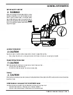
Page 5: ... OFF position set the Parking Brake 24 and disconnect the batteries before performing any service function Never work under a machine without safety blocks or stands to support the machine Make sure the Hopper Safety Support 37 is in place whenever attempting to do any maintenance work under or near the raised hopper Never operate this machine near flammable liquids or vapors Do not clean this mac...

Page 6: ...e machine on an open truck or trailer make sure that All access doors are latched securely The machine is tied down securely see tie down locations 34 _________________________________________________________________________________________________________________________________________________________________________________________________________________________________________________________...

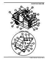
Page 7: ...Amp Dust Control Shaker Motor 9 Circuit Breaker 6 Amp Aux Circuit 1 10 Circuit Breaker 10 Amp Side Broom Motor 11 Circuit Breaker 5 Amp Aux Circuit 2 12 Circuit Breaker 60 Amp Hydraulic Pump 13 Circuit Breaker 40 Amp Main Broom Motor 14 Circuit Breaker 80 Amp Wheel Drive Motor 15 Main Broom Raise Lower ON OFF Lever 16 Hopper Raise Lower Lever 17 Hopper Door Open Close Lever 18 Hopper Cover 19 Dust...

Page 8: ...FORM NO 56041389 Retriever 4600 6 KNOW YOUR MACHINE 1 2 3 4 7 5 6 8 9 10 11 12 13 14 15 17 16 CONTROL PANEL 22 23 31 34 34 34 35 29 40 42 42 43 42 ...

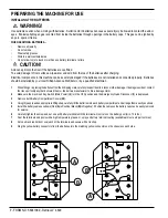
Page 9: ...alled and connected properly Batteries should be installed by your local Nilfisk Advance Distributor or by a qualified electrician 1 Whenfittingorreplacingthebatteriesfromtheirshippingcrate carefullyinspectthemforcracksorotherdamage Ifdamageisevident contact the transport company that delivered them or the battery manufacturer to file a damage claim 2 Make sure the machine s Key Switch Main Power ...

Page 10: ...e brooms when the batteries are re charged ______________________________________________________________________________________________________________________________________________________________________________________________________________________________________________________________________________________________________________________________________ EMPTYING THE HOPPER NOTE The M...

Page 11: ...ore detail on maintenance and service repairs ______________________________________________________________________________________________________________________________________________________________________________________________________________________________________________________________________________________________________________________________________ EVERY 30 HOURS OF OPERATION...

Page 12: ...___________________________________________________ CHECKING THE BATTERY ELECTROLYTE LEVEL Check the electrolyte level of the batteries at least once a week After charging the batteries remove the vent caps and check the electrolyte level in each battery cell Use distilled water to fill the batteries to the bottom of the filler tube Do not over fill the batteries CAUTION Acid can spill onto the fl...

Page 13: ...room Motor always turns in the same direction the bristles on the broom eventually become curved reducing sweeping performance Sweeping performance can be improved by removing the broom and turning it around end for end This procedure known as rotating the main broom should be done once every 30 hours of operation The main broom should be replaced when the bristles are worn to a length of 2 1 2 in...

Page 14: ..._____________________________________________________________________________________________________________________________________________________________________________ HOPPER DUST CONTROL FILTER The hopper dust control filter must be cleaned regularly to maintain the efficiency of the vacuum system Follow the recommended filter service intervals for the longest filter life CAUTION Wear safet...

Page 15: ...ician check the machine Main Broom Motor Circuit Breaker 40 Amp Possible cause may be 1 Debris wrapped around the broom drive or broom remove debris 2 Main broom set too low adjust main broom 3 Electrical short circuit have your Nilfisk Advance Service Center or qualified electrician check the machine Side Broom Motor Circuit Breaker 10 Amp Possible causes may be 1 Debris wrapped around the broom ...

Page 16: ..._________________ SIDE BROOM WILL NOT RUN Possible causes may be 1 Hopper door is not open open hopper door 2 Side Broom Motor Circuit Breaker 10 tripped reset circuit breaker 3 Debris wrapped around the broom drive remove debris 4 Aux Circuit 1 Circuit Breaker 9 tripped reset circuit breaker __________________________________________________________________________________________________________...

Page 17: ...395 20 hr Protection Grade IP30 Sound Power Level ISO 3744 dB A 20µPa 72 Net Weight w o batteries lbs kg 2 040 925 Gross Weight w batteries lbs kg 2 760 1 252 Vibrations at the Hand Controls m s2 2 5 Vibrations at the Seat m s2 0 5 ________________________________________________________________________________________________________________________________________________________________________...

Page 18: ...Nilfisk Advance Inc 14600 21st Avenue North Plymouth MN 55447 3408 www nilfisk advance com Phone 800 989 2235 Fax 800 989 6566 2000 Nilfisk Advance Inc Plymouth MN 55447 3408 Printed in the U S A ...

Reviews: