


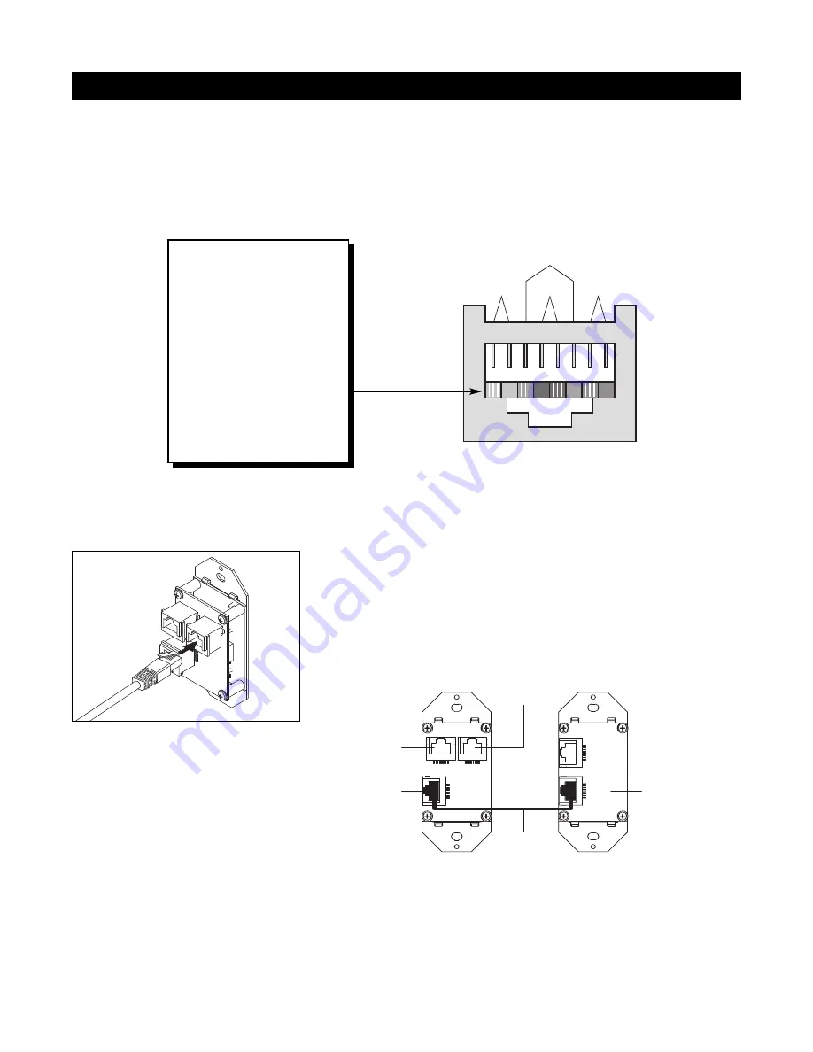
TERMINATING FOUR-PAIR TWISTED CABLE
The Solo
™
Master Keypad Modules, the Expander, and the ZR-4630’s System Expansion connections require a
four-pair twisted cable with a one-to-one wiring configuration. To maintain consistency throughout all Intellipad
Ci installations, we recommend the color-coding pattern described in Figure 31. However, you may follow the
color-coding pattern of your choice, as long as it is used consistently throughout the system.
45
CONNECTIONS
12 3 4
Pair 2
Pair 1
T568A
Pair 3
Pair 4
567 8
1 = Green/White
2 = Green
3 = Orange/White
4 = Blue
5 = Blue/White
6 = Orange
7 = Brown/White
8 = Brown
Figure 31
Solo
™
Master
Keypad Module
Numeric
™
Accessory
Keypad Module
RJ-45 Connector for
connection to Master
Keypad Module
RJ-45 Connector
for connection to
Numeric Accessory
Keypad Module
RJ-45 Connector
for connection to
IR Sensors
RJ-45 Connector for
connection to
the ZR-4630
Included
Jumper Cable
IR SENSOR
INPUT
OUTPUT
SYSTEM
ACCESSORY
KEYPADS
Figure 32
Figure 33
CONNECTING
NUMERIC
™
KEYPADS
Each Solo
™
Master Keypad Module
can be mated with one optional
Numeric
™
Accessory Keypad Module
using an included jumper cable (see
Figure 33).
CONNECTING THE SOLO
™
MASTER KEYPADS TO THE
HOME RUN OF FOUR-PAIR TWISTED CABLE
The home run of four-pair twisted cable is terminated with a male
RJ-45 connector and plugged into the rear panel jack labeled SYSTEM
on the Solo
™
Master Keypad Module (see Figure 32).
Summary of Contents for ZR-4630 ZR-4630
Page 81: ...73 NOTES ...


