background image


This document may be subject to change    


Side 7 of 24


Ducting 

We recommend that there are used ducts and fittings with rubber packing that meet sealing class 
B and that the connections between the unit and the ducting are made with 1 metre sound absorb-
ing flexible transitions as regards sound reduction. 
 
The ducts should be shortened with a hacksaw or an angle grinder and laid out according to the 
working drawing. The ducts are typically laid out on the main beam of the truss frame and are se-
cured with hole belts or they are being hanged in assembly belts. Please avoid any unnecessary 
area reductions and breaks of the ducting. 
 
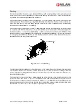
The ducts should be insulated – in some cases with the ordinary attic-insulation. All ducts should 
be insulated with 100mm mineral wool to avoid heat loss and condensation. This also applies for 
flexible transitions. It is recommended that the insulation is carried out with 2 layers of 50mm. If the 
ducts are laid out in an unheated room it will cause condensation problems if the unit are turned off 
for a longer period of time as the hot air from the heated room will rise to the ducts and cause con-
densation which can cause damp problems. 


Figure 4: Insulation of ducting 


The discharge duct is leading the exhaust air away either above the roof or through the outer wall.  
It is important that the roof cowl has at least the same open space as the duct leading to the roof 
cowl. A reduction at this place will cause an unnecessary pressure drop which can lead to a re-
duced ventilation output. 
 
The holes for the inlet- and exhaust valves should be cut according to the mounting-frame for the 
prescribed valve. The frame for the valve must be secured with screws before placing the valve in 
the frame. The valves are placed in accordance with the size, construction and use of the room. As 
an example we would not recommend placing an inlet valve just above people with sedentary work 
because the inlet air in some cases would be experienced as a draught. 
 

Granulate


Duct


Loft insulationmaterial


Summary of Contents for Combi 302 Polar Top

Page 1: ...Version 10 00 28 11 2016 Combi 302 Polar Installation instruction CTS 602 by Nilan...

Page 2: ...re parts 24 Figure table Figure 1 CTS 602 control 4 Figure 2 Mounting the Combi 302 Polar 5 Figure 3 Condensation drain water seal 6 Figure 4 Insulation of ducting 7 Figure 5 CTS 602 control 8 Figure...

Page 3: ...elivery of the Combi 302 Polar is with filter classes F5 EU5 in the exhaust device and F7 EU7 in the injection The unit can be equipped with different accessories e g hygrostat and filter box with pol...

Page 4: ...eler prevents fur ther cooling of the building if the primary heat supply stops by stopping the ventilation if the panel feeler gets below a specific value Factory setting is 10 C the value can be set...

Page 5: ...es a clearance height of minimum 11 5 cm under the outlet connection piece It is not necessary to re insulate the system as it is delivered with a 20 mm standard insulation The system is low noise and...

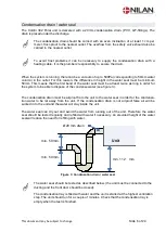
Page 6: ...ice as long in order for the system to be able to dispose of the condense water see figure 3 The condensation drain must be airproof from the unit to the water seal in order for the condensa tion wate...

Page 7: ...ers of 50mm If the ducts are laid out in an unheated room it will cause condensation problems if the unit are turned off for a longer period of time as the hot air from the heated room will rise to th...

Page 8: ...gh the service menu of the CTS 602 control For daily use of the CTS 602 control please see the CTS 602 directions delivered together with the Combi 302 Polar Use of t he CTS 600 panel pr ess ESC t o g...

Page 9: ...isplay Press ENTER to activate the SERVICE menu It is then possible to scroll through the SERVICE menu options using the p buttons The options available on the SERVICE menu are shown in the figure bel...

Page 10: ...ough the menus or to adjust the setting of an activated menu option ENTER to activate a menu option ENTER to confirm a menu option setting OFF switch off the controls ON to switch on the controls DEFR...

Page 11: ...ROL PRESET OFF RESTART OFF ROOM CONTROL AIR EXCHANGE INLET HEATING AIR QUALITY MANUAL OFF MODBUS ADR 30 DATALOG INTV 10 Forsinkelse fra opstart af bl sere og varmekrav til eftervarmefladen frigives 0...

Page 12: ...menus or to adjust the setting of an activated menu option ENTER to activate a menu option ENTER to confirm a menu option setting OFF switch off the controls ON to switch on the controls DEFROST FUNCT...

Page 13: ...u option ENTER to confirm a menu option setting OFF switch off the controls ON to switch on the controls Each ventilation step can be set as a percentage of maximum fan INLET HEATING AIR EXCHANGE ENTE...

Page 14: ...ST ENTER AIR EXCHANGE INLET CONTROL SERVICE ENTER TEMP CONTROL RESTART OFF MANUAL OFF PRESET OFF ROOM CONTROL AIR QUALITY MODBUS ADR 30 DATALOG INTV 10 HEAT SURFACE Lockout between 2 defrost periods C...

Page 15: ...MP CONTROL ENTER AIR EXCHANGE DEFROST INLET CONTROL SERVICE ENTER RESTART OFF MANUAL OFF PRESET OFF ROOM CONTROL EXTERNAL 1 C AIR QUALITY Option for an extra heating element via relay output R8 R8 is...

Page 16: ...through the menus or to adjust the setting of an activated menu option ENTER to activate a menu option ENTER to confirm a menu option setting OFF switch off the controls ON to switch on the controls I...

Page 17: ...a menu option ENTER to confirm a menu option setting OFF switch off the controls ON to switch on the controls INLET HEATING ROOM CONTROL TEMP CONTROL AIR EXCHANGE DEFROST INLET CONTROL SERVICE ENTER R...

Page 18: ...s through the menus or to adjust the setting of an activated menu option ENTER to activate a menu option ENTER to confirm a menu option setting OFF switch off the controls ON to switch on the controls...

Page 19: ...activated menu option ENTER to activate a menu option ENTER to confirm a menu option setting OFF switch off the controls ON to switch on the controls INLET HEATING AIR EXCHANGE DEFROST INLET CONTROL...

Page 20: ...witch off the controls ON to switch on the controls AIR QUALITY AIR EXCHANGE DEFROST INLET CONTROL SERVICE ENTER TEMP CONTROL PRESET OFF ROOM KONTROL RESTART OFF MANUAL OFF MANUAL OFF ENTER MANUAL DEF...

Page 21: ...s or to adjust the setting of an activated menu option ENTER to activate a menu option ENTER to confirm a menu option setting OFF switch off the controls ON to switch on the controls AIR QUALITY AIR E...

Page 22: ...ariables Din and Dout Options that flash are indicated by On the CTS602 control panel press ESC to return to the previous menu p to scroll upwards or downwards through the menus or to adjust the setti...

Page 23: ...This document may be subject to change Side 23 of 24 System dimension Combi 302 Polar 1 Aussenluft 2 Zuluft 3 Abluft 4 Fortluft 10 Stromversorgung 11 Kondens Ablauf Figure 20 System dimension...

Page 24: ...This document may be subject to change Side 24 of 24 Accessories spare parts Combi 302 Polar Filter types Qty Nilan item no Filter sheet G4 8 pcs 1 391713 Filter cassette F7 1 39520...

Reviews: