


11
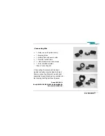
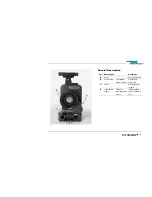
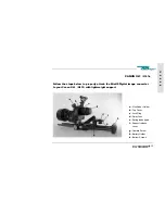
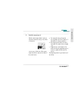
Pos. Description
Comment
L
REMOTE
input
3 Pin Fisher
female socket
Pin 1 – GND
Pin 2 – N.C.
Pin 3 – VTR
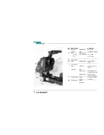
M
INPUT
(for LANC
cable)
7 Pin Fischer
female socket
Pin 1 – not
connected
Pin 2 – VTR trigger
Pin 3 – Bat +
Pin 4 – U Bat ex
Pin 5 – not
connected
Pin 6 – Bat -
Pin 7 – RET
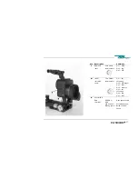
N
Control LED
RUN
LOW BAT
GREEN
Æ
RED
(low power)
Æ
Blinking light
Æ
Good speed control
Acceptable speed
Below minimum
speed
Summary of Contents for Image Converter
Page 1: ...1 Image Converter User Manual Model Oszi 400 Series ...
Page 2: ...2 ...


