VBA10201-R.3577.A
-
A25
・
-
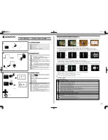
3. Outer LCD Unit, Command Dials and Top Cover FPC
ON
OFF
s
WB
M
P
S
A
QUAL
ISO
FOR
MAT
①
Affix the C/D FPC #B1018 on the outer LCD Unit and
fix it on the top cover using the screw #655 x 4.
②
Attach the release switch unit B354, and main and
sub-command dials on the top cover.
③
Remove the connecctor A of the top cover FPC #B2002,
and then insert it in the connector A of the outer LCD unit.
④
Attach the top cover FPC #B2002 to the top cover and
make the soldering bridges.
Soldering Bridge between
the SP Up FPC and
Top
cover FPC
Soldering bridge between
the mode dial FPC and
top cover FPC
#807
A
A
Blue
:AE-L
White
:
〃〃
Soldering bridge between
the C/D FPC and command
dial
Yellow
:
Metering Mode
Black
: 〃 〃
Black
: 〃 〃
B
B
C
C
#643
B2002
#654
#725
#340
#339
#342
#773
B1018
#655x5
B325
#613
#328
#666
B354
B1373
B330
#655x2
#655x2
#341
#343
B359
B360
After attaching tapes#488x2 to
top cover, make holes by some
sharp point tool in order to
prevent from rolling in.
#488x2
①
①
②
②
● Tighten the screws in order
of
①
to
② .
Summary of Contents for D100 VBA10201
Page 19: ...VBA10201 R 3577 A D13 Prism Box Unit 1 Removal of Prism Box Unit from Front Body 688x4 ...
Page 21: ...VBA10201 R 3577 A D15 AF Sensor Unit TTL SPD Unit 170x3 602x3 B2163 B2004 625x2 200 ...
Page 27: ...VBA10201 R 3577 A D21 Bottom Plate Unit 607x2 677x2 832x2 830 103 102 677 109 101 66 ...
Page 81: ... ...
Page 83: ... ...


