background image

30

s

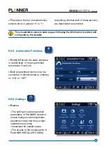
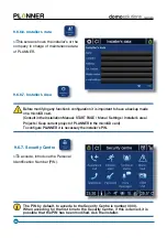
Show the state of those sensors 

connected to PLANNER, which is of 
interest for the user to visualize its state.

s

The analog sensor state (upper part 

of screen), shows the sensor’s defined 
value at scale in every moment in the 
measure unit (physical magnitude). It can 
be defined a white or red line to indicate 
if the sensor in any moment is below or 
above an established limit.
 

9.6.4. Sensors Information

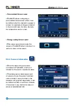
Personalized Screen saver

s

PLANNER allows configuring a 

personalized screen saver where it can 
be defined what it is desired to appear in 
screen, for example an image contained 
in the microSD card, the time, the date, 
the temperature and/or a text.

Energy saving Screen saver  

s

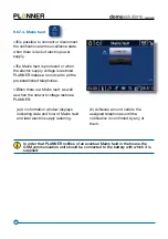
This screen saver disconnects the 

screen of PLANNER after 3 minutes if no 
action is done on the screen. 

Summary of Contents for domosolutions PLANNER

Page 1: ...USER S MANUAL...

Page 2: ...simulator Scenes Screen saver Programming Shutters Lighting Temperature Messages Air Conditioning Comfort Heating Energy meter Intrusion Alarm Water Gas Smoke Technical Alarms Mains Fault Alarm Securi...

Page 3: ...e 13 9 1 1 Lighting 14 9 1 2 Shutters 15 9 1 3 Scenes 15 9 1 4 Favorites 16 9 1 5 Home Control from the telephone GSM 17 9 2 Messages 18 9 3 Intrusion Control 20 9 4 Technical Alarms 20 9 5 ASSISTANCE...

Page 4: ...6 9 6 7 3 Technical Alarms 37 9 6 7 4 Mains fault 38 9 6 7 5 Telephones 39 9 6 7 6 Passwords 40 9 6 7 7 Voice messages 41 9 6 7 8 GSM Unit con guration 42 9 6 7 9 Security Centre Control from the tele...

Page 5: ...ns of comfort safety and energy saving all this with an intuitive handling s It is possible to interact with PLANNER in two ways LOCAL COMMUNICATION Through a tactile screen REMOTE COMMUNICATION Throu...

Page 6: ...void direct sun rays proximity to television lamps chimneys heating pipes and any element producing heat Avoid PLANNER proximity to electromagnetic elds Always keep an updated copy of the con guration...

Page 7: ...l to use in the tactile screen to select functions and to write messages on the screen s To extract it slide the nger on the right low part of the frame and push the pencil towards the right s The pre...

Page 8: ...t included It has a slot to introduce a card of microSD memory s To insert or extract the memory use the pencil at the back side INSERTION EXTRACTION Do not assembly or disassembly the frame with the...

Page 9: ...isconnection of lighting circuits Shutters Move up move down groups of shutters Scenes Activate a scene THERMOSTAT Connect disconnect the thermostat function Configure the operation mode SECURITY CENT...

Page 10: ...NER nishes the call and continues the round of due calls s When PLANNER noti es an incident in the house by telephone and the user con rms from his telephone the reception of this noti cation pressing...

Page 11: ...Alarm clock and countdown function s Allows activating an alarm or countdown of a noti cation clock which emits an acoustic signal at the programmed hour s The icon shows the state activated deactivat...

Page 12: ...access to it s Shows the state of the most important PLANNER functions GSM network coverage Intrusion Alarm Technical Alarm and Thermostat s If GSM unit is not installed no icon will be shown 3 Tempe...

Page 13: ...ment Grey colour icon indicates that the air conditioning is disconnected in that moment s The activated winter mode of the thermostat has two options Blue colour icon indicates that the heating is co...

Page 14: ...activated Stand by programmed activated Protection programmed activated Disconnection programmed activated 5 Time and calendar 6 Favourites s Shows the time in screen s To see the calendar press on t...

Page 15: ...start screen press placed in the top part of the screen s Access to the functions of lighting connection disconnection and temporization of automatisms shutters control as well as to the activation of...

Page 16: ...or or slide the cursor to turn on turn off or regulate the light DIMMER TYPE BUTTON s Press ON if you want to turn on the light press OFF if you want to turn it off SWITCH TYPE BUTTON s Press ON for l...

Page 17: ...otion press any of the two push buttons and it will stop s PLANNER allows the shutters activating s Select the push button SHUTTERS 9 1 2 Shutters s o s The scenes grouped to different actions which a...

Page 18: ...ede quickly to the most used lighting shutters or scene functions to ed lightin s In the different menus of Home the icon is shown which allows incorporating or eliminating a lighting or scene functio...

Page 19: ...s case option 1 Now you can work with your PLANNER You can also hang up the telephone when you wish If you want to check the alarms state please press 0 If you wish to take an action on any of the ava...

Page 20: ...ages on the screen and read SMS text messages sent to PLANNER from a telephone s Select Messages in the Start Menu s The state of a message is shown as follows Indicates that the message is not read I...

Page 21: ...shown in the screen Date and time of edition of the message From to edit the text of the person who sends the message To to edit the text of the recipient of the message Press to edit the text of the...

Page 22: ...roduction of PIN s The function is also accessible from the Security Centre See Section 9 6 7 2 Intrusion Alarm s It is shown in the Start Menu when con gured by installer 9 3 Intrusion Alarm s This p...

Page 23: ...activates the Assistance Alarm s The activation of the Assistance Alarm activates the acoustic alarm of PLANNER calls to the list of telephones assigned to this alarm and activates the automatisms con...

Page 24: ...se the timer program and nished when determined with an END value The time zones can be different throughout the different days of the week s It is possible to determine up to two time zones for each...

Page 25: ...use s It is also necessary to program reference temperatures so the function CLIMATE can manage both heating and air conditioning s PLANNER can be managed in Manual Mode or Program Mode 9 6 2 Thermost...

Page 26: ...g In the case one of these two installations is not available PLANNER will only show the installed option s Select or depending on the season s The status bar will show the active mode or s Select the...

Page 27: ...ure for its use at night s In summer this function maintains the Temperature of the house below the reference Temperature s In winter this function maintains the Temperature of the house over the refe...

Page 28: ...peration sequence corresponding to the day of the week selected i th 9 6 2 2 PROGRAM MODE Climate management Anti freeze and overheat protection s The aim of this operation mode is In winter to preven...

Page 29: ...oughout the day s To nish select s To copy the con guration to other days select s Determine the days where it is desired to copy the programming s Press again to nish s When activating the Program Mo...

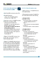
Page 30: ...Function two 3 Function three 4 Thermostat 5 Intrusion Alarm s When selecting option 4 for Thermostat PLANNER will inform you of the state Your thermostat is controlling cool Mode SUMMER heat Mode WIN...

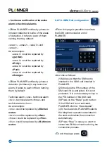
Page 31: ...images contained in the folder selected from a microSD card The recommended resolution is 320 x 240 pixels s The photo frame type screen saver is shown during 15 minutes s The screen saver of PLANNER...

Page 32: ...ed line to indicate if the sensor in any moment is below or above an established limit 9 6 4 Sensors Information Personalized Screen saver s PLANNER allows con guring a personalized screen saver where...

Page 33: ...f PLANNER Select of screen background and lightness adjustment date and time screen calibration and tones Visualizes the installer s data The access to the con guration of PLANNER INSTALLER S AREA 9 6...

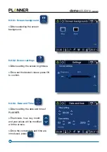
Page 34: ...ll be modi ed with the arrows s Once the correct date and time are introduced press 9 6 6 3 Date and Time ct date an s Allows selecting the screen background 9 6 6 1 Screen background s Allows setting...

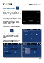
Page 35: ...The calibration should be done pressing on the 4 points shown in the screen When pressing on them the button changes of state to indicate that the pressing has been done s Press ACCEPT to keep the cal...

Page 36: ...dified Ask the installer 9 6 6 7 Installer s Area Before modifying any function s configuration it is important to have a backup made on a microSD card Consult in the Installation Manual START PAGE Me...

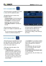
Page 37: ...e noti cation telephones 9 6 7 2 Intrusion Alarm s From this page it is possible to connect and disconnect the Intrusion Alarm and the detection areas which have to be active in the alarm detection s...

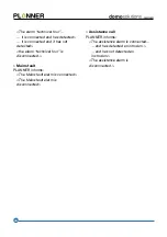
Page 38: ...m s From this page before an intrusion detection in any of the areas you can a Cut the call round to the intrusion incidence noti cation telephones b Disconnect the established action c Disconnect the...

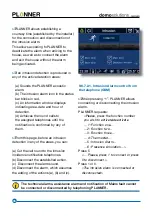
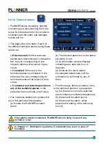
Page 39: ...bar the icon blinks in red colour s If an incidence detection is produced in any of the active technical alarms a Sounds the PLANNER acoustic alarm b The intrusion alarm icon in the status bar blinks...

Page 40: ...blished telephones s When there is a Mains fault as well as when the network voltage restores PLANNER a An information window displays indicating date and hour of Mains fault and later electric supply...

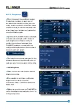
Page 41: ...er to notify To modify the number of attempts that PLANNER makes to contact with the con gured telephones and the number of tones of each call select s The telephone numbers assigned to the different...

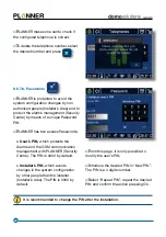
Page 42: ...has two access Passwords User s PIN which protects the Alarms and the GSM communication management with PLANNER Security Centre The PIN is 0000 by default Installer s PIN which avoids changes in the...

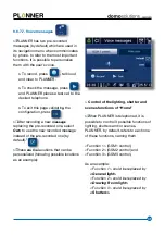
Page 43: ...lect Own to use the new recorded message instead of the pre recorded one by default s These are the locutions that can be personalized following possible locutions as an example Control of the lightin...

Page 44: ...e replaced by Kitchen water two could be replaced by Gas three could be replaced by Fire four could be replaced by Bathroom water s From this page is possible to activate the GSM communication unit of...

Page 45: ...etected the alarm technical three is disconnected 9 6 7 9 Control Security Centre from the telephone GSM s Call PLANNER and introduce the PIN s PLANNER answers Hello this is PLANNER please introduce y...

Page 46: ...s not detected an instrusion The assistance alarm is disconnected The alarm technical four it is connected and has detected it is connected and it has not detected the alarm technical four is disconne...

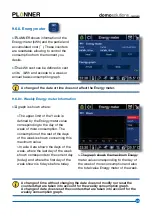
Page 47: ...ys of the week is shown concerning this maximum value In axle X are shown the days of the week where the last day of the week shown corresponds to the current day today and where the rst day of the we...

Page 48: ...raph show the maximum Energy meter value corresponding to the month of the year of more consumption the Energy meter value along the year and the annual total value A change of time without changing t...

Page 49: ...onnected stop the phone calls round and disconnect the alarm Section 9 6 7 2 Intrusion Alarm s In case of receiving the intrusion noti cation phone call you could con rm the alarm from the telephone b...

Page 50: ...LANNER can be disconnected stop the phone calls round and disconnect the alarm Section 9 6 7 3 Technical Alarms s In case of receiving the incidence noti cation phone call of any of the Technical Alar...

Page 51: ...ne calls round and disconnect the alarm Section 9 6 7 1 Assistance Alarm s In case of receiving the assistance noti cation phone call you could con rm the alarm from the telephone by pressing Thus the...

Page 52: ...ns Displays an information window which indicates the date and time of the Mains fault and later electric supply voltage restoration Makes the telephone calls round assigned until the noti cation is c...

Page 53: ...alog outputs Voltage Output 1 to 10Vdc Current of maximum charge 50mA Maximum number of connectable ballasts 15 Each output has 2 terminals with polarity SCREEN AUDIO Screen Hitachi 5 7 TFT CCFL LCD d...

Page 54: ...data s User s PIN s Phone Number SIM card s SIM card PIN s SIM card PUK s PLANNER Installation date Installer Details Notes Company stamp s Name s Company s Phone s E mail...

Page 55: ...Asea Brown Boveri S A NIESSEN FACTORY Pol Ind Aranguren 6 20180 Oiartzun Spain Tel 34 943 260 101 Fax 34 943 260 250 79N96320ENG 1...

Reviews: