2018.01 / g
Electric Power Generation
19
Installation and maintenance
R449 revision f
AVRs
3983 en -
3.6 - 1F LV PMG excitation
Page 1: ...X2 X1 Z2 E E 0V 110 220 380 Z1 R449 R449 revision f AVRs Installation and maintenance...
Page 2: ...nel Warning symbol for electrical danger to personnel All servicing or repair operations performed on the AVR should be undertaken by personnel trained in the commissioning servicing and main tenance...
Page 3: ...16 3 4 AREP 3F MV excitation 17 3 5 1F LV shunt booster excitation 18 3 6 1F LV PMG excitation 19 4 COMMISSIONING 20 4 1 In case of standalone regulation 20 4 2 In case of 1F regulation parallel opera...
Page 4: ...ulator includes a main terminal strip 10 terminals J1 a secondary terminal block 5 terminals J2 a frequency selection terminal block 3 terminals J3 a quadrature droop potentiometer P1 a voltage potent...
Page 5: ...aristor 5 6 T7 T8 T9 T10 T11 T12 R449 Aux windings 10 Yellow 11 Red 9 Green 12 Black STATOR 6 or 12 wire marking T1 to T12 MAIN FIELD ST5 with LAM without LAM P5 Excitation ceiling ST11 ST2 ST1 knee p...
Page 6: ...R449 ST5 P5 ST11 ST2 ST1 P3 P2 Tension R731 ST4 Option T I Option S1 S2 14 15 16 PMG PMG SYSTEM Field Armature Aux windings STATOR 6 or 12 wire marking T1 to T12 MAIN FIELD with LAM without LAM Excit...
Page 7: ...9 T10 T11 T12 R449 ST5 P5 ST11 ST2 ST1 P3 P2 Tension R731 ST4 Option T I Option S1 S2 SHUNT SYSTEM Field Armature STATOR 6 or 12 wire marking T1 to T12 MAIN FIELD with LAM without LAM Excitation ceili...
Page 8: ...E TENSION EXTERIEUR EXTERNAL VOLTAGE POTENTIOMETRE BORNIER CONNECTOR J1 SOUS VITESSE UNDERFREQUENCY LIMITE D EXCITATION EXCITATION LIMIT TEMPS TIME RESISTANCE RESISTOR EXCITATEUR EXCITER TRANSISTOR DE...
Page 9: ...ge setting ST4 A F Internal 1 3 5 Power supply The power can be supplied using 2 independent auxiliary windings integrated in the alternator stator AREP excitation using a single or 3 phase power VT u...
Page 10: ...0 with LAM Time without LAM 1 s 2 s 3 s 1 3 10 3 Power 0 1 s 2 s 3 s Time LAM Variation in the load Load on the shaft kW Load shedding due to LAM 1 3 11 Gradual voltage return function During load imp...
Page 11: ...fall back automatically to a value less than 1A To reset switch off the power supply using the circuit breaker A Note After setting the upper excitation limit using this procedure re adjust the voltag...
Page 12: ...ion 12 Installation and maintenance R449 revision f AVRs 3983 en 2 R726 REGULATION OF POWER FACTOR 2F AND MAINS SENSING 3F The power factor and mains sensing are done by the R726 module See the specif...
Page 13: ...7 6 5 4 3 2 1 400 0 S1 S2 T3 T2 T1 1 2 3 4 5 6 7 8 9 10 LED P3 P4 P1 ST1 ST2 MAINS VOLTAGE PHASES 2 3 GENERATOR VOLTAGE PHASES 2 3 RED GREEN U U Cos J1 P5 C1 C2 P6 U VOLTAGE U U Cos Cos J2 TI CT 1A P...
Page 14: ...ion 14 Installation and maintenance R449 revision f AVRs 3983 en 3 TYPICAL DIAGRAMS The following diagrams are supplied for information only and are not to be used in place of the actual alternator di...
Page 15: ...2018 01 g Electric Power Generation 15 Installation and maintenance R449 revision f AVRs 3983 en 3 2 AREP 1F MV excitation...
Page 16: ...2018 01 g Electric Power Generation 16 Installation and maintenance R449 revision f AVRs 3983 en 3 3 AREP 3F LV excitation...
Page 17: ...2018 01 g Electric Power Generation 17 Installation and maintenance R449 revision f AVRs 3983 en 3 4 AREP 3F MV excitation...
Page 18: ...2018 01 g Electric Power Generation 18 Installation and maintenance R449 revision f AVRs 3983 en 3 5 1F LV Shunt Booster excitation...
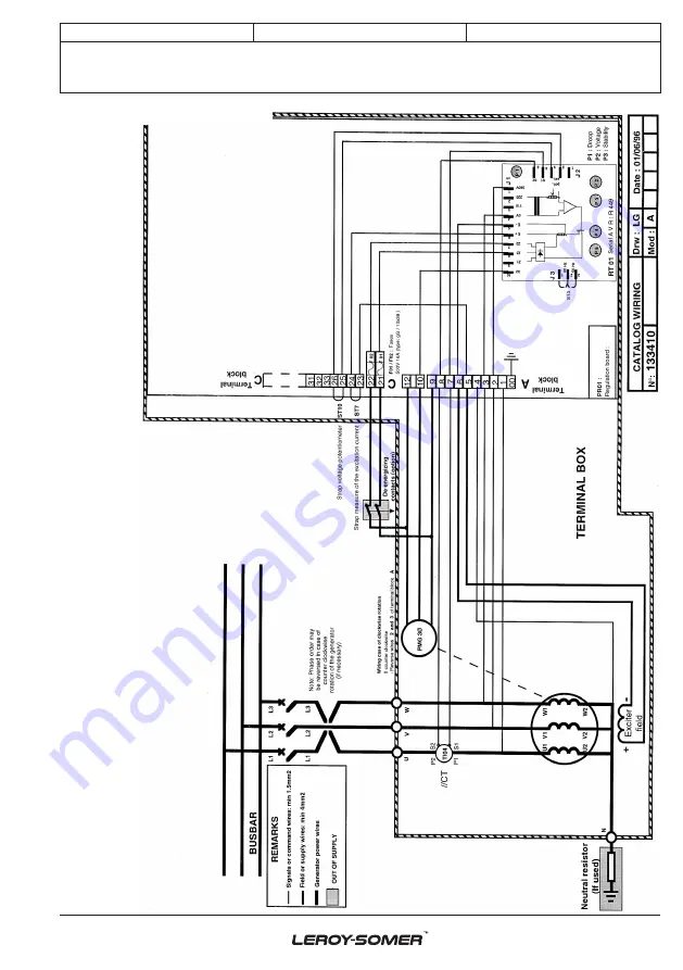
Page 19: ...2018 01 g Electric Power Generation 19 Installation and maintenance R449 revision f AVRs 3983 en 3 6 1F LV PMG excitation...
Page 20: ...inductive load the voltage drops This voltage drop is set using quadrature droop potentiometer P1 The no load voltage is always greater than the on load voltage if thevoltagerises inverttheparallelop...
Page 21: ...reaker is closed The green LED on the R726 lights up Open contact 3F and remove the mains voltage reference Preset the PF potentiometer P2 to 5 and limit potentiometer P4 to 3 5 Without supplying kW p...
Page 22: ...voltages are at their rated values and are balanced at 1 for the given excitation value the machine is operating correctly and the fault is due to the regulation part regulator wiring sensing auxiliar...
Page 23: ...the load from the alternator Check the wiring Test it or change it Check the exciter and the diodes Replace the fuses Voltage too high and adjustment potentiometer not operating Incorrect voltage at...
Page 24: ...t identical Phases not connected to the sensing correctly The CT is not on the correct phase Adjust the quadrature droop potentiometer Check that all the alternators have the same no load voltage valu...
Page 25: ...ternator characteristics 5 4 Replacing the regulator with a spare voltage regulator Set the potentiometers and the jumpers in the same way as the original regulator 6 SPARE PARTS 6 1 Designation Descr...
Page 26: ...mply with local legislation regarding product disposal and recycling Waste hazardous materials The following components and materials require special treatment and must be separated from the alternato...
Page 27: ...ent repair support and maintenance services Trust your alternator maintenance and support to electric power generation experts Our field personnel are 100 qualified and fully trained to operate in all...
Page 28: ...2018 01 g www leroy somer com epg 3983 en Linkedin com company Leroy Somer Twitter com Leroy_Somer_en Facebook com LeroySomer Nidec en YouTube com LeroySomerOfficiel...