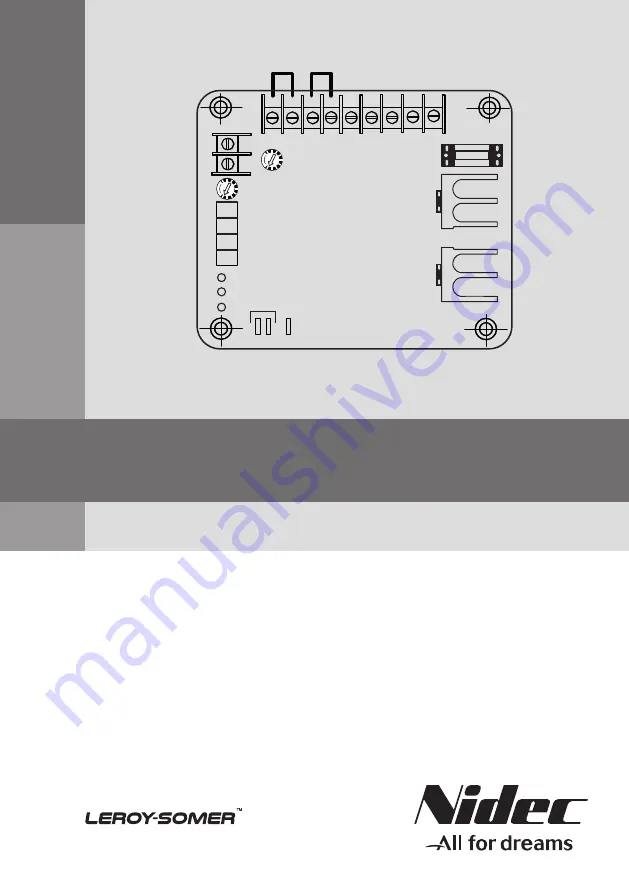
R2
Droop
50 Hz
VACSUFOE
SLUFOE
60 Hz
R1
A1A2
Q2 Q1 F2 F1 N
FUSE
W V
R150
AVRs
Installation and maintenance
Page 1: ...R2 Droop 50 Hz V AC S UF OE SL UF OE 60 Hz R1 A1 A2 Q2 Q1 F2 F1 N FUSE W V R150 R150 AVRs Installation and maintenance...
Page 2: ...rning symbol for electrical danger to personnel All servicing or repair operations performed on the AVR should be undertaken by personnel trained in the commissioning servicing and main tenance of ele...
Page 3: ...IN FUNCTION OF THE AVR 6 5 AVR SETTINGS 7 5 1 V TRIM V 7 5 2 FRO UF 7 5 3 STAB S 7 5 4 EXC LIMIT OE 7 5 5 QUADRATURE DROOP 7 5 6 A1 A2 DC VOLTAGE INPUTS AC 7 6 AVR CONTROLS 7 7 TROUBLESHOOTING CHART 8...
Page 4: ...circuit continuously monitors the generator underspeed protection by reducing the generator output voltage in proportion with the speed below a threshold The AVR has the facility for droop CT connecti...
Page 5: ...ge regulation 0 8 at the AVR terminals 14 Thermal drift 1 for a 30 C change in temperature 15 Response time less than 50 ms 16 Closed loop response typically 0 5 sec to recover 98 of the defined volta...
Page 6: ...sects the amplified voltage at a point which is early or late in the half cycle At this intersection point a starting pulse is produced to trigger the power device Only qualified personnel should repl...
Page 7: ...r clockwise will result in a sluggish response and possibly also oscillations The factory default setting is slightly higher than critical damping around halfway 5 4 EXC LIMIT OE This function is prov...
Page 8: ...oltmeter on the front defective Check and correct AVR defective repeated fuse blowing Replace after performing a static test Earthed exciter field Check and correct High voltage build up Loose or miss...
Page 9: ...hould be approximately 2 2 MW in the 10 MW range and vice versa with the multimeter jack common applied to the AVR F2 terminal should be 15 MW ZERO indicates power device failure in both cases Nofurth...
Page 10: ...ockwise the lamp should go out slowly Now turn the UF potentiometer clockwise The lamp should glow brightly again 5 It is difficult to prescribe a static test for checking the stability as this is mor...
Page 11: ...1 g 11 Electric Power Generation 135 mm 115 mm 110 mm 90 mm 10 10 R2 Droop 50 Hz V AC S UF OE SL UF OE 60 Hz R1 A1 A2 Q2 Q1 F2 F1 N FUSE W V R150 Installation and maintenance R150 AVRs 5384 en 10 DIME...
Page 12: ...ion you may require For all spare parts orders or technical support requests send your request to service epg leroy somer com or your closest contact whom you will find at www lrsm co support indicati...
Page 13: ...ith local legislation regarding product disposal and recycling Waste hazardous materials The following components and materials require special treatment and must be separated from the alternator befo...
Page 14: ...2018 01 g 14 Electric Power Generation Installation and maintenance R150 AVRs 5384 en...
Page 15: ...ent repair support and maintenance services Trust your alternator maintenance and support to electric power generation experts Our field personnel are 100 qualified and fully trained to operate in all...
Page 16: ...2018 01 g www leroy somer com epg 5384 en Linkedin com company Leroy Somer Twitter com Leroy_Somer_en Facebook com LeroySomer Nidec en YouTube com LeroySomerOfficiel...