


7
Maintenance and service guide - LSN-FLSN ZONE
2 - Ex ec
5724 en - 2020.02 / c
3.2 - Checking the insulation
Throughout the period required for checking insulation, ensure
that there is no explosive atmosphere present.
Before operating the motor we
recommend checking the insulation between
phases and earth and between phases.
Motors are factory-fitted with preventative advice labels
which must kept legible.
Before commissioning remove condensation (see §10.4
- ROUTINE MAINTENANCE)
This check is essential if the motor has been stored for longer
than 6 months or if it has been kept in a damp atmosphere.
This measurement must be carried out using a megohmmeter
at 500 volts DC (do not use a magneto-electric system).
It is better to carry out an initial test at 30 or 50 volts and if the
insulation is greater than 1 megohm, carry out a second test at
500 volts DC for 60 seconds. The insulation value must be at
least 10 megohms in cold state.
If this value cannot be achieved, or routinely if the motor might
have been splashed with water or salt spray, or kept for a long
period in a very humid place, or if it is covered with condensation,
it is recommended that the stator be dried for 24 hours in an
oven at a temperature of 110 °C to 120 °C.
If it is not possible to dry the motor in an oven:
- supply the motor, with the rotor immobilised, with a
three-phase AC voltage which is 10% below the rated voltage,
for 12 hours (use an induction regulator or a step-down
transformer with adjustable points).
- or supply it with DC supply with the 3 phases in series, with a
voltage value of 1 to 2% of the rated voltage (use a separate
excitation DC generator or batteries for motors of less than 22 kW).
- NB: The AC current must be monitored using a clamp-on
ammeter, DC using a shunt ammeter. This current must not
exceed 60 % of the rated current.
It is recommended that a thermometer be fitted to the motor
frame: if the temperature exceeds 70 °C, reduce the indicated
voltage or current by 5 % of the original value for every 10 °C
difference.
While it is drying, all the motor orifices must be open (terminal
box, drain holes). Before starting replace all plugs so that the
motor exhibits the plated degree of protection. Clean the
orifices and plugs before refitting them.
Warning! Since the high voltage test was carried
out at the factory before dispatch. If it needs to be
repeated, this should be performed at half the standard
voltage, i.e.: 1/2 (2U+1000V). Check that the capacitive
effect resulting from the high voltage test is eliminated
before connecting the terminals to ground.
For all motors before commissioning:
- remove the dust from the entire machine
- rotate the motor at no load (no mechanical load) for 2 to
5 minutes, checking that there is no abnormal noise. If
there is any abnormal noise, see section 10.
4 - INSTALLATION
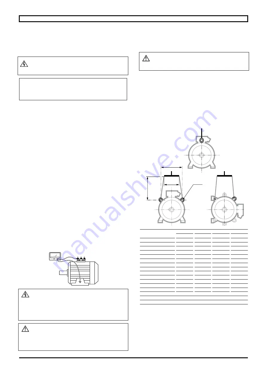
4.1 - Position of the lifting rings
The lifting rings are provided for lifting
only the motor. They must not be used to lift the
machine after the motor has been fitted to it.
Labour regulations stipulate that all loads over 25 kg must be
fitted with lifting devices to facilitate handling.
The overall mass of motors can vary according to their power,
their mounting position and whether the motors are fitted with
optional equipment. The actual weight of each Nidec Leroy-
Somer motor is indicated on its nameplate. The positions of the
lifting rings and the minimum dimensions of the loading bars
are given below in order to help with preparation for handling
the motors. If these precautions are not followed, there is a risk
of warping or crushing some equipment such as the terminal
box, protective cover or drip cover.
Type
Horizontal position
A
e min
h min
Øt
100
120
200
150
9
112
120
200
150
9
132
160
200
150
9
160
200
160
110
14
180 MR
200
160
110
14
180 L
200
260
150
14
200
270
260
165
14
225 ST/MT
270
260
150
14
225 M
360
265
200
30
250
360
380
200
30
280
360
380
500
30
315 S
310
380
500
17
315 M/L
360
380
500
23
355
310
380
500
23
355 LK - 400
735
710
500
30
400 LK - 450
730
710
500
30
M
e
A
h
2 x Øt
• Horizontal position
INSTALLATION AND MAINTENANCE – LSN-FLSN ZONE 2 – Ex ec


