Rev. 1 - 05/10/2021
OPERATING MANUAL
OPERATING MANUAL
EN
EN
51/56
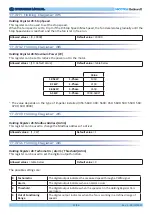
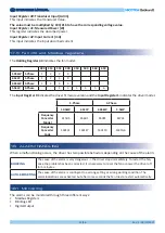
17.5 Fan info and Modbus registers
The
Holding Register 44 indicates the fan model.
280 315 355 400 450
500
560
630
1.05kW 1-Phase
1
2
3
4
-
-
-
-
2.1kW
1-Phase
1
2
3
4
-
-
-
-
2.65kW 3-Phase
1
2
3
4
-
-
-
-
5.5kW
3-Phase
-
-
1
2
3
4
5
6
The
Input Register 0 indicates the driver firmware version and the Input Register 1 indicates the driver model.
1-Phase
3-Phase
1.05kW
2.1kW
2.65kW
5.5kW
Frequency
Converter
Model
41505
45601
45091
61731
Frequency
Converter
Code
1431C1
1431E7
1431F0
1431G6
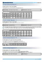
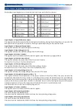
Input Register 30: Transducer Input [Adim]
This input indicates the Transducer Value.
The value must be multiplied by 10V/216 to have the corresponding voltage value.
Input Register 31: Measured Power [W]
This register indicates the absorbed power.
Input Register 32: Input Current [mA]
This input indicates the input absorbed current.
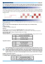
18. ALARM HANDLING
When a malfunctioning occurs, the driver has two possible behaviors depending on the cause of the alarm:
BLOCKING
The cause of the alarm is very dangerous -> The driver stops immediately. To restart the fan,
once the problem has been corrected, it is necessary to reset the fan or power the driver off
for 5 minutes.
AUTO-RESTARTING
The cause of the alarm is contingent to a wrong setting or wrong working condition. The
alarm indications are activated, but after some seconds the fan tries to restart automatically.
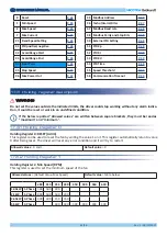
The alarms can be monitored through three different ways:
• Modbus Registers
• Blinking LED
• Digital Output
18.1 Monitoring


