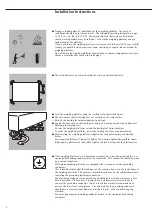
Nicol Scales & Measurement Sartorius Combics CAPXS Series Operating Instructions Manual Download Page 7

6

Installation

§

Connect the cable of the weighing platform to a suitable indicator, such as the FCT01-X

from Sartorius.

Note:
The cable gland on Sartorius indicators is installed at the factory.  Please use extreme

caution when performing any work on the equipment that affects this cable gland.

§

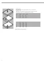
Remove the casing from a length of the cable end and install the cable as follows:

– Remove the screw fastener from the cable gland and slide it over the end of the cable.
– Remove the casing from a section of the cable end (see illustration).  The shielding (1)

must have contact with the clamps (2).  Fold back 3 to 4 mm of the shielding so that it
overlaps the O-ring (see illustration).

– Expose approximately 15 cm (4 inches) of the wires (3) for connection within the

terminal.

– Thread the cable through the cable gland.
– Make sure the shielding is in contact with the clamps.  The shielding supplies the

grounding connection.

– Replace the screw fastener and tighten it securely.

§

Connect the wire ends to the terminal strip:

– Remove the casing from a section of the cable end.  Expose enough of the wires in the

cable for installation.

–  Remove the casing from approx. 1 cm (0.5 in.) of the wires and affix ferrules to the

wire ends.

– Slide the enclosed protective sleeve over all the wires down to the cable gland, so that

no more than 5 cm of the wires is exposed between the end of the sleeve and the
terminal strip.

– Attach the wires securely to the screw terminals (blue = positive, brown or black =

negative)

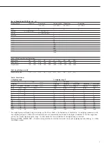
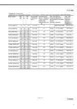
Color Codes in the Weighing Platform Connecting Cable, Model CAPXS..

No. Signal des.

Meaning

Color of wire casing

1

BR_POS

Bridge supply voltage (+)

blue

2

SENSE_POS

Sense (+)

green

Bridge supply voltage

3

OUT_POS

Measuring voltage positive

white

4

OUT_NEG

Measuring voltage (-)

red

5

SENSE_NEG

Sense (-)

gray

Bridge supply voltage

6

BR_NEG

Bridge supply voltage (-)

black or brown

§

Use a screwdriver to tighten the terminal screws.

Note on connecting the FCT01-X:
The bridge supply voltages are protected by 62mA fuses.  To prevent the fuses
from reacting if wires are incorrectly connected, resistors between pin 1 and
pin 6, between pin 1 and the housing and between pin 6 and the housing must
measure greater than 140 ohms.  Low-ohm connections are also required between
pins 1 and 2 and between pins 5 and 6.

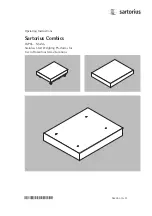
Summary of Contents for Sartorius Combics CAPXS Series

Page 1: ...ustin Ft Worth NicolScales com 800 225 8181 Contact Us Nicol Scales Measurement is an ISO Accredited Calibration Company that has provided calibration repair and sales of all types of weighing and mea...

Page 2: ...98648 010 95 Operating Instructions Sartorius Combics CAPXS Models Stainless Steel Weighing Platforms for Use in Hazardous Areas Locations...

Page 3: ...ve the following warning and safety information in its entirety during installation and operation as well as while performing maintenance and repair work on the equipment It is important that all pers...

Page 4: ...Always make sure the weighing platform is disconnected from AC power before performing any installation cleaning maintenance or repair work If the equipment housing is opened by anyone other than per...

Page 5: ...ockwise To lower the weighing platform retract the leveling feet turn counterclockwise After leveling the weighing platform retighten the lock nuts securely as described below Low capacity platforms 1...

Page 6: ...with a 3 m cable for connecting the indicator See also the Certificate of Proof of Intrinsic Safety in the appendix to this manual The explosion protected weighing system must be installed in accordan...

Page 7: ...n of the cable end Expose enough of the wires in the cable for installation Remove the casing from approx 1 cm 0 5 in of the wires and affix ferrules to the wire ends Slide the enclosed protective sle...

Page 8: ...0 000d 1 x 3000e _____ range range 1 _____ Range 1 range 2 Range 2 in kg in g in g in g in kg in kg in g in kg in g 3 0 2 0 1 1 3 1 5 0 5 3 1 6 0 5 0 2 2 6 3 1 6 2 15 1 0 5 5 15 6 2 15 5 30 2 1 10 30...

Page 9: ...of the load center side one sided corner load the maximum capacity of the weighing platform is as follows Model Center Side Corner DC 50 35 20 ED 130 85 45 FE 300 200 100 GF 450 300 150 IG 900 600 30...

Page 10: ...of the inside of the scale or flush out using a gentle stream of water 60 C max Make sure that no debris builds up in the gap between the load receptor and the fastening plate to avoid compromising th...

Page 11: ...ndustrial areas continuously monitored operation Limitation of emmissions Residential areas Class B Important Note The operator shall be responsible for any modifications to Sartorius equipment and fo...

Page 12: ...EG01CWS 1000 x1000 1000 YEG02CWS 1250 x 1000 1000 YEG03CWS 1500 x 1250 1250 YEG04CWS 1500 x 1500 1500 YEG05CWS 2000 x 1500 1500 YEG06CWS Roller conveyor stainless steel for platform sizes Size in mm A...

Page 13: ...12 EC Type Approval Certificate...

Page 14: ...13...

Page 15: ...14...

Page 16: ...15...

Page 17: ...15...

Page 18: ...16...

Page 19: ...17...

Page 20: ...18...

Page 21: ...19...

Page 22: ...20...

Page 23: ...21...

Page 24: ...22...

Page 25: ...23...

Page 26: ...24...

Page 27: ...25...

Page 28: ...26...

Page 29: ...27...

Page 30: ...28...

Page 31: ...29...

Page 32: ...30...

Page 33: ...31...

Page 34: ...eans without the prior written permission of Sartorius AG The status of the information specifications and illustrations in this manual is indicated by the date given below Sartorius AG reserves the r...

Reviews: