background image

EN

English – 

15

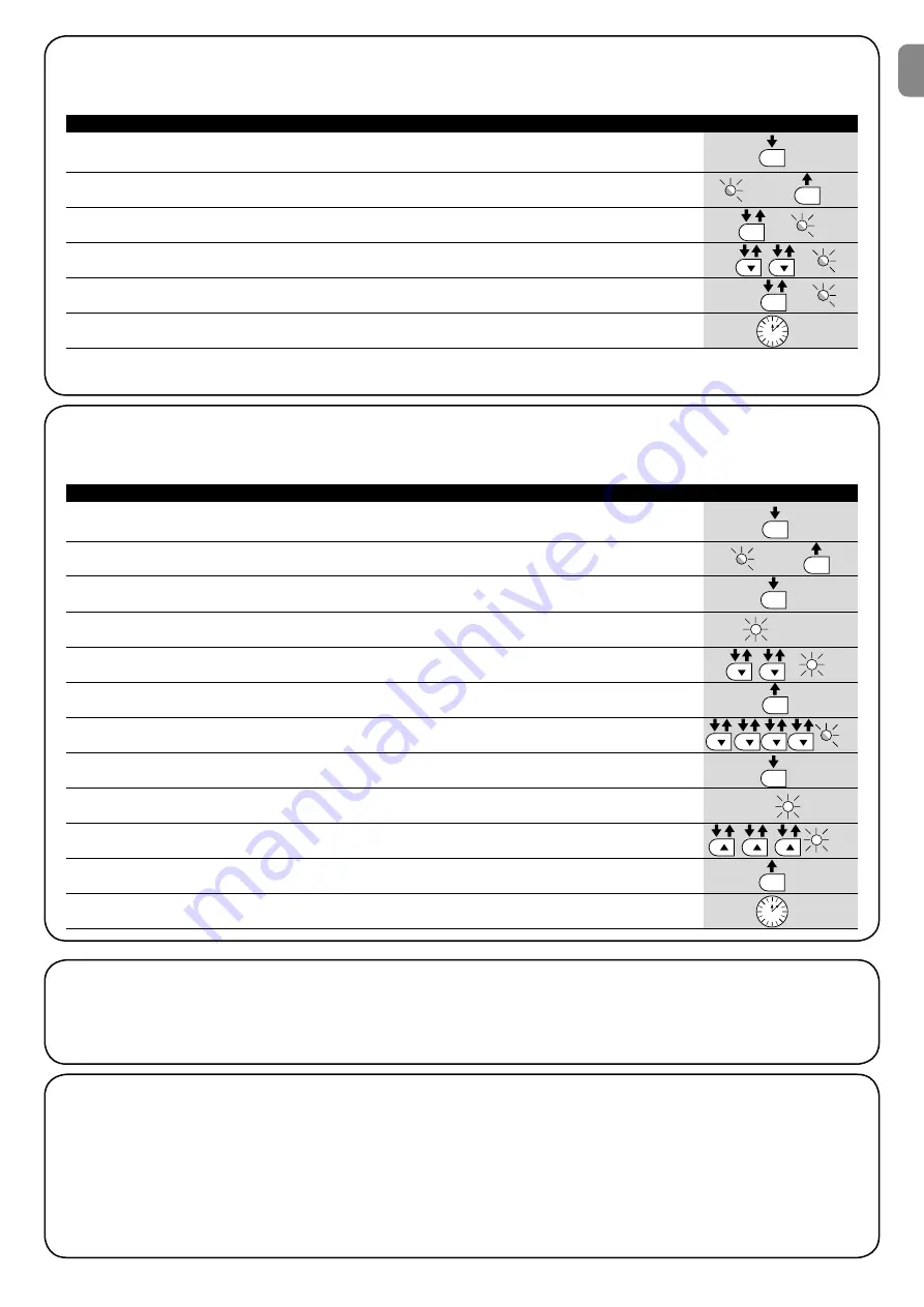
7.2.6) Level two programming example (adjustable parameters)

The sequence to follow in order to change the factory settings of the parameters increasing the “Pause Time” to 60 seconds (input on L1 
and level on L5) and reducing the “Motor Force” for light gates (input on L5 and level on L2) have been included as examples

1.


Press the key 

[Set]

 and hold it down (approx. 3 s) 


3s

2.


Release the 

[Set] 

key when L1 LED starts flashing 


L1

3.


Press the key 

[Set]

 and hold it down during step 4 and 5


4.


Wait approx. 3 seconds until LED L3, representing the current level  


of the “Pause Time” will light up 

L3 

3s

5. 

Press the 

[

t

]

 key twice to move the LED which is lit to LED L5, 


which represents the new “Pause Time” value  

L5

6. 

Release the key 

[Set]

  
7. 

Press the 

[

t

]

 key four times to move the flashing LED to LED L5


L5

8. 

Press the key 

[Set]

; and hold it down during step 9 and 10


9.


Wait approx. 3 seconds until LED L5, representing the current


level of the “Motor Force” will light up 

3s 

L5

10.


Press the 

[

s

]

 key three times to move the LED which is lit to LED L2,


which represents the new “Motor Force” value 

L2

11.


Release the key 

[Set]

12.


Wait 10 seconds before leaving the programme to allow the maximum time to lapse.


 10s

Table 10: Level two programming example 

Example

SET

SET

SET

SET

SET

SET

7.3) Adding or removing devices

Devices can be added to or removed from the ROBUS automation 
system at any time. In particular, various devices types can be con-
nected to “BLUEBUS” and “STOP” input as explained in the follow-
ing paragraphs.

After you have added or removed any devices, the automa-
tion system must go through the recognition process again 
according to the directions contained in paragraph 7.3.6 
“Recognition of other devices”.

7.3.1) BLUEBUS

BLUEBUS technology allows you to connect compatible devices 
using only two wires which carry both the power supply and the 
communication signals. All the devices are connected in parallel on 
the 2 wires of the BLUEBUS itself. It is not necessary to observe any 
polarity; each device is individually recognized because a univocal 
address is assigned to it during the installation. Photocells, safety 
devices, control keys, signalling lights etc. can be connected to 
BLUEBUS. The ROBUS control unit recognizes all the connected  

 
devices individually through a suitable recognition process, and can 
detect all the possible abnormalities with absolute precision. For this 
reason, each time a device connected to BLUEBUS is added or 
removed the control unit must go through the recognition process; 
see paragraph 7.3.6 “Recognition of Other Devices”.

7.2.5) Level one programming example (ON-OFF functions)

The sequence to follow in order to change the factory settings of the functions for activating “Automatic Closing” (L1) and “Always close” 
(L3) have been included as examples.

1.


Press the key 

[Set]

 and hold it down (approx. 3 s)  


3s

2.


Release the 

[Set]

 key when L1 LED starts flashing 


L1

3.


Press the 

[Set]

 key once to change the state of the function associated with L1 


Automatic Closing). LED L1 will now flash with long flashes. 

L1

4.


Press the 

[

t

]

 key twice to move the flashing LED to LED L3


L3

5. 

Press the 

[Set]

 key once to change the state of the function associated with L3 


(Always Close). LED L3 will now flash with long flashes. 

L3

6. 

Wait 10 seconds before leaving the programme to allow the maximum time to lapse.


10s

Once these operations have been completed, LEDs L1 and L3 must remain on to indicate that the “Automatic Closing” and the “Always 
Close” functions are active. 

Table 9: Level one programming example 

Example

SET

SET

SET

SET

Summary of Contents for ROBUS RB1000

Page 1: ...Sliding gate opener ROBUS RB400 RB600 600P RB1000 1000P RB250HS RB500HS Instructions and warnings for installation and use ...

Page 2: ... Disposal 11 7 Additional information 12 7 1 Programming keys 12 7 2 Programming 12 7 2 1 Level one functions ON OFF functions 12 7 2 2 Level one programming ON OFF functions 13 7 2 3 Level two functions adjustable parameters 13 7 2 4 Level two programming adjustable parameters 14 7 2 5 Level one programming example ON OFF functions 15 7 2 6 Level two programming example adjustable parameters 15 7...

Page 3: ...ed before it has been commissioned as specified in the chapter on Testing and commis sioning The packing materials of the product must be disposed of in compliance with local regulations Before proceeding with the installation of the product check that all materials are in good working order and suited to the intended applications The manufacturer assumes no liability for damage to property items ...

Page 4: ...cular sliding gate depends on the friction as well as other correlated factors such as ice that could interfere with the movement of the leaf For an effective control it is absolutely vital to measure the force nec essary to move the leaf throughout its entire run and ensure that this is less than half of the nominal torque indicated in chapter 8 Tech nical characteristics a 50 margin on the force...

Page 5: ...ust be totalle d then the estimated durability in the graph must be checked with the total result For example when ROBUS 1000 is fitted to a gate weighing 650 kg and 5m in length equipped with photocells and without other stress related elements it obtains a severity index equal to 50 30 10 10 From the graph the estimated durability is equal to 80 000 cycles Table 2 durability estimate in relation...

Page 6: ... larger gauge e g 3x2 5mm2 and that a safety grounding system is provided near the automation unit Note 2 If the BLUEBUS cable is longer than 30 m up to 50 m a 2x1mm2 cable is needed Note 3 A single 2x0 5mm2 cable can be used instead of two 4x0 5mm2 cables Note 4 Please refer to Chapter 7 3 2 STOP Input in situations where there is more than one edge for information about the type of con nection r...

Page 7: ...esulting values with those specified in Chapter 8 Technical Characteristics The manufacturers recommend a 50 margin on the force as unfavourable climatic conditions may cause an increase in the friction Make sure that there are no points of greater friction in the opening or closing travel of the gate leaves Make sure there is no danger of the gate derailing Make sure that the mechanical stops are...

Page 8: ...vement paragraph in the Chapter Instructions and Warnings for Users 8 9 10 11 12 If the rack is already present once the gearmotor has been fastened use the adjustment dowels as shown in Figure 8 to set the pinion of ROBUS to the right height leaving 1 2 mm of play from the rack Otherwise in order to fasten the rack the installer must 6 Release the gearmotor as shown in Release and manual move men...

Page 9: ...ne along the cables until you reach the clamp Then put the membrane back in the slot of the hole the cables pass through Lay a second clamp for collecting the cables which are set just above the membrane 4 Connect the power cable to the appropriate terminal as shown in figure 15 then block the cable at the first cable block ring using the clamp 5 Connect up the other cables according to the diagra...

Page 10: ...he position of the gearmotor with respect to the leaf If the leaf must move left for opening the selector must be moved towards left as shown in Figure 18 alternatively if the leaf has to move right during opening the selector must be moved towards the right as shown in Figure 19 18 19 4 2 Power supply connection The connection of ROBUS to the mains must be made by qualified and experienced person...

Page 11: ...mand Output N 2 Partial opening command Output N 3 Open command Output N 4 Close command Table 4 commands with transmitter This is the most important stage in the automation system installa tion procedure in order to ensure the maximum safety levels Testing can also be adopted as a method of periodically checking that all the various devices in the system are functioning correctly Testing of the e...

Page 12: ...f conformity of the automation system and deliver it to the owner 5 Prepare the Instructions and warnings for the use of the automa tion system and deliver it to the owner 6 Prepare the maintenance schedule of the automation system and deliver it to the owner it must provide all directions regarding the maintenance of the single automation devices 7 Before commissioning the automation system infor...

Page 13: ...After 5 seconds the gate will begin to close automatically The Close after photo function is always disabled in manoeuvres interrupted by a Stop command If the Close after photo function is inactive the pause time is that which has been programmed or there is no automatic closing if the function is inactive L3 Always Close The Always Close function will trigger and the gate will close if an open g...

Page 14: ...he modifications made up to that stage 1 Press the key Set and hold it down approx 3 s 3s 2 Release the Set key when L1 LED starts flashing L1 3 Press keys s or t to move the flashing LED onto the LED representing the function which is to be changed or 4 Press the Set key to change the state of the function short flashing OFF long flashing ON 5 Wait 10 seconds before leaving the programme to allow...

Page 15: ...t this becomes Open partially Adjusts the number of manoeuvres after which it signals the maintenance request of the automation see paragraph 7 4 3 Maintenance warning The type of defect that has occurred in the last 8 manoeuvres can be established see paragraph 7 6 1 Malfunctions archive L6 L7 L8 7 2 4 Level two programming adjustable parameters The adjustable parameters are factory set as shown ...

Page 16: ...aph 7 3 6 Recognition of other devices 7 3 1 BLUEBUS BLUEBUS technology allows you to connect compatible devices using only two wires which carry both the power supply and the communication signals All the devices are connected in parallel on the 2 wires of the BLUEBUS itself It is not necessary to observe any polarity each device is individually recognized because a univocal address is assigned t...

Page 17: ...n the photocell instruction manual 7 3 3 Photocells By means of addressing using special jumpers the BLUEBUS system enables the user to make the control unit recognise the photocells and assign them with a correct detection function The addressing operation must be done both on TX and RX setting the jumpers in the same way making sure there are no other couples of photocells with the same address ...

Page 18: ...en choosing one must consider the convenience of the connections and the fact that the Step by Step command of the Slave only allows the Slave leaf to be opened fully Connect the 2 motors as shown in fig 26 Select the opening direction of the 2 motors as shown in fig 25 see also paragraph 4 1 Choosing the direction Supply power to the 2 motors Program the Slave mode on the ROBUS Slave see table 5 ...

Page 19: ...en programmed 7 4 Special functions Table 12 ROBUS Slave programming independent from ROBUS Master Level one functions ON OFF functions Level two functions adjustable parameters Stand by Motor speed Peak Open Gate Indicator Output Slave Mode Motor force Error list On Slave it is possible to connect A flashing light Flash An open gate light S C A A sensitive edge Stop A command device Step by Step ...

Page 20: ...e warning function Follow the indications in table 15 for this control Table 15 control of the number of manoeuvres performed Example SET SET SET SET n Manoeuvre counter reset After the maintenance of the system has been performed the manoeuvre counter must be reset Proceed as described in table 16 1 Press the key Set and hold it down approx 3 s 3s 2 Release the Set key when L1 LED starts flashing...

Page 21: ... is voltage on the flashing light s FLASH terminal during the manoeuvre being intermittent the voltage value is not important approximately 10 30Vdc if there is voltage the problem is due to the lamp in this case replace the lamp with one having the same characteristics if there is no voltage there may have been an overload on the FLASH output Check that the cable has not short circuited Check the...

Page 22: ...to BLUEBUS do not correspond to those recognized during the recognition phase One or more devices may be faulty check and if necessary replace them in case of modi fications repeat the recognition process 7 3 4 Recognition of Other Devices 7 7 1 Flashing light signalling During the manoeuvre the flashing light FLASH flashes once every second When something is wrong the flashes are more frequent th...

Page 23: ...it means that the user must carry out the device recognition phase refer to Paragraph 4 3 Recognition of the devices On It flashes Off During normal operation the device indicates Always close is not active During normal operation the device indicates Always close is active During normal operation the device indicates Stand by is not active During normal operation the device indicates Stand by is ...

Page 24: ...the weight and length limits given in table 2 Durability Estimated between 20 000 and 250 000 cycles depending on the conditions given in Table 2 Power input 230Vac 10 15 50 60Hz Thrust maximum absorbed power equivalent to amperes 330W 2A 3 9A version V1 515W 2 5A 4 8A version V1 450W 2 3A 4 4A version V1 330W 2A 3 9A version V1 330W 2 5A 4 8A version V1 Insulation class 1 a safety grounding syste...

Page 25: ...the following stand ards EN 61000 6 2 2005 EN 61000 6 3 2007 A1 2011 The product also complies with the following directives according to the requirements envisaged for quasi machinery Directive 2006 42 EC OF THE EUROPEAN PARLIAMENT AND COUNCIL of 17 May 2006 related to machinery and which amends the directive 95 16 EC recast It is hereby declared that the pertinent technical documentation has bee...

Page 26: ... that maintenance checks be carried out every six months for normal domestic use but this interval may very depending on the intensity of use Only qualified personnel are authorised to carry out checks maintenance operations and repairs Do not modify the system or its programming and adjustment parameters in any way even if you feel capable of doing it your installation technician is responsible f...

Page 27: ...ined the gate will keep moving as soon as the control is released the gate will stop If the safety devices are out of order the auto mation must be repaired as soon as possible Replacing the Remote Control Battery if your radio control after a period of time seems not to work as well or not to work at all it may simply be that the bat tery is exhausted depending on the type of use it may last from...

Page 28: ......

Reviews: