Nice PP7124 Instructions And Warnings For Installation And Use Download Page 5

ENGLISH – 

5

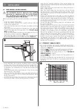
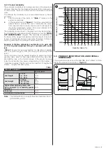
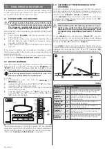
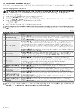
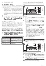
3.2.1 Product durability

The product’s durability is its average economic life value and is 

strongly influenced by the degree of severity of the manoeuvres: 

in other words, the sum of all factors that contribute to product 

wear.

To estimate the durability of your automated device, proceed 

as follows:

1. 

add the values of the items in “

Table 1

”  relative  to  the 

system’s conditions

2. 

in the graph shown in “

Figure


4

”, from the value obtained 

above, trace a vertical line until it intersects the curve; 

from this point trace a horizontal line until it intersects the 

line of the “manoeuvre cycles”. The value obtained is the 

estimated lifetime of your product.

The durability values shown in the graph can only be obtained if 

the maintenance schedule is strictly observed – see the “

PROD-

UCT MAINTENANCE

” chapter. The durability is estimated on 

the basis of the design calculations and the results of tests ef-

fected on prototypes. Being an estimate, therefore, it offers no 

explicit guarantee of the product’s actual useful life.

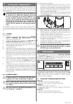
Example of lifetime calculation: automation of a gate with 

a 1.3 m-long leaf weighing 180 kg, for example with a solid 

leaf.

Table 1

” shows the “severity indices” for this type of installa-

tion: 15% (“Door length”), 30% (“Door weight”) and 15% (“Solid 

leaf”).

These indicators must be added together to obtain the overall 

severity index, which in this case is 60%. With the value iden-

tified (60%), look at the horizontal axis of the graph (“severity 

index”) and identify the value corresponding to the number of 

“manoeuvre cycles” that the product can perform throughout its 

lifetime – roughly 100,000 cycles.

Table 1

PRODUCT DURABILITY

Severity index

Leaf length

< 1,0 m

1,0 - 1,5 m

1,5 - 2,0 m

0%

15%

20%

Leaf weight

< 100 kg

100 - 150 kg

150 - 200 kg

0%

20%

30%

Ambient temperature greater than 

40°C or below 0°C, or humidity greater 

than 80%

20%

Solid leaf

15%

Installation in windy areas

15%

Note

  The data refers to a properly balanced sectional door in 

good working order.

50000

100000

150000

200000

250000

Durability in cycles (No.)

Severity index (%)

4

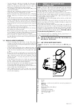
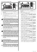
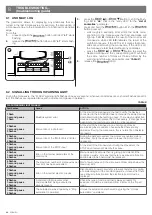
3.3  PRODUCT IDENTIFICATION AND OVERALL 

DIMENSIONS

The overall dimensions and the label (

A

), which allows for iden-

tifying the product, are shown in “

Figure


5

”.

315 mm

167 mm

254 mm

A

5

Summary of Contents for PP7124

Page 1: ...Nice PP7124 Swing gate opener EN Instructions and warnings for installation and use...

Page 2: ...ion process handle the product with care by avoiding crushing impacts falls or contact with liquids of any kind Do not place the product near sources of heat nor expose it to open flames All these act...

Page 3: ...ontrolled by a fire sensing system make sure that any windows larger than 200 mm are closed using the control elements Prevent and avoid any form of entrapment between the moving and fixed parts durin...

Page 4: ...iquids keep the product away from heat sources and open flames and acid saline or potentially explosive atmospheres these may damage the product and cause malfunctions or danger ous situations if ther...

Page 5: ...t s actual useful life Example of lifetime calculation automation of a gate with a 1 3 m long leaf weighing 180 kg for example with a solid leaf Table 1 shows the severity indices for this type of ins...

Page 6: ...ommended 5 m 4 BLUEBUS DEVICES cable 1 cable 2 x 0 5 mm2 Maximum length 20 m note 2 5 KEY SELECTOR cable 2 cables 2 x 0 5 mm2 note 3 Maximum length 50 m 6 ELECTRIC LOCK cable 1 cable 2 x 1 mm2 Maximum...

Page 7: ...resulting opening angle 3 with the value of distance A and the opening angle found using the graph to determine the distance B For example if A is 100 mm and the desired angle is equal to 100 distanc...

Page 8: ...racket for the gate leaf I to the curved arm F D H F I G G H 15 10 unlock the gearmotor manually see paragraph Manually unlocking and locking the gearmotor 11 decide where to attach the bracket to the...

Page 9: ...mit switch A as shown in the figure 4 loosen the screw that fastens the straight arm to the gear motor 5 apply the protective cover B and re tighten the screw with the washer A B 19 6 move the gate to...

Page 10: ...nection under the Category III overvoltage conditions in accordance with the installation instructions To make the electrical connections 1 open the gearmotor s cover A A 21 2 pass the power cable and...

Page 11: ...Example EPM EDSB ETPB For further information on the BlueBUS refer to the BlueBUS paragraph Stop Input for devices that suspend or even stop the current manoeuvre Normally Closed and Normally Open co...

Page 12: ...EBUS L1 L2 26 The learning process of connected devices can be repeated at any time even after the installation for example whenever a device must be added to complete the new learning process refer t...

Page 13: ...signal the current position STOP SBS OPEN BLUEBUS L1 29 To effect the manual learning procedure 1 simultaneously press and hold the and g buttons h 2 release the buttons when LED L1 starts flashing af...

Page 14: ...on to be programmed 5 proceed for each individual position as described in the Learning in manual mode paragraph 6 repeat this last operation for all the other positions to be modified 5 4 CHECKING TH...

Page 15: ...impact force it is neces sary to test various adjustments to find the one that gives the best results 6 2 COMMISSIONING a Commissioning can only be performed after all test ing phases have been succe...

Page 16: ...ing will not take place if the function is disabled L3 Always Close Function ENABLED in the event of a blackout even of short duration if the control unit detects that the gate is not closed once the...

Page 17: ...omatic Closing is enabled L2 15 seconds L3 30 seconds L4 45 seconds L5 60 seconds L6 80 seconds L7 120 seconds L8 180 seconds L2 Step by Step function L1 Open Stop Close Stop Controls the sequence of...

Page 18: ...d M2 opens to 110 the minimum opening is 90 L2 Pedestrian 2 the M2 gate leaf opens to 1 2 of the full range L3 Pedestrian 3 the M2 gate leaf opens to 3 4 of the full range L4 Pedestrian 4 full opening...

Page 19: ...he limit Lit for 2 seconds at the start of the opening manoeuvre Between 81 and 100 of the limit Flashes for the entire duration of the manoeuvre Exceeding 100 of the limit Flashes always 7 4 3 Verify...

Page 20: ...uring the learning phase There may be defective devices check and replace them if necessary if changes have been made the learning procedure must be repeated 2 flashes 1 second pause 2 flashes Interve...

Page 21: ...r to that shown in Table 8 STOP LED OFF Intervention of the STOP input Check the devices connected to the STOP input On Everything normal STOP input active Sbs LED OFF Everything normal Sbs input not...

Page 22: ...ices can be connected to each other in parallel Any number of NC devices can be connected to each other in series Two devices with 8 2 k fixed resistor output can be connect ed in parallel if there ar...

Page 23: ...commands shown in Table 12 Table 12 OXI IN EXTENDED MODE II No Command Description 1 Step by Step SbS Step by Step command 2 Partial opening 1 Partial opening 1 command 3 Open Open command 4 Close Cl...

Page 24: ...p the spring G by its two ends 6 thread the other end of the cable through the hole located on the lower part of the gearmotor 7 put the cover back on A A C B G D E F 44 8 connect the cable to Kio by...

Page 25: ...B in the appropriate slot C on the control unit s electronic board 3 insert the cable D in the appropriate slot E on the in terface C B D E A 45 4 At this stage the control unit can be powered again l...

Page 26: ...ST NOT BE POWERED by the elec tricity grid at the same time l For information on the Solemyo system consult the relevant instruction manual To connect the Solemyo system 1 remove the cover A 2 remove...

Page 27: ...components replace any worn parts 5 connect the power supplies again and run all the tests and checks described in the Testing paragraph PRODUCT DISPOSAL 11 11 PRODUCT DISPOSAL l This product is an in...

Page 28: ...que 10 minutes Application limits The product can be used on gates with leaves weighing up to 200 kg for lengths up to 2 m Durability Estimated between 80 000 and 250 000 cycles depending on the condi...

Page 29: ...cated fixing plate Operating temperature 20 C 55 C at low temperatures the gearmotor s efficiency decreases Use in highly acid saline or potentially explosive atmosphere No Protection rating IP 44 wit...

Page 30: ...lowing directives according to the requirements envisaged for partly completed machinery Annex II part 1 section B Directive 2006 42 EC of the EUROPEAN PARLIAMENT AND COUNCIL of 17 May 2006 related to...

Page 31: ...ENGLISH 31 NOTES...

Page 32: ...32 ENGLISH NOTES...

Page 33: ...uipped with back up batteries the automation can none theless be used by manually unlocking the motor consult the instructions at the end of the chapter and moving the gate leaf manually Safety device...

Page 34: ...has come to a standstill To unlock the device 1 raise the small cover 2 insert the key A and turn it clockwise by 90 A 48 3 the gate leaf can now be moved manually to the desired position To lock the...

Page 35: ...ENGLISH 35 NOTES...

Page 36: ...www niceforyou com Nice SpA Via Callalta 1 31046 Oderzo TV Italy info niceforyou com IDV0668A00EN_31 01 2019...

Reviews: