background image

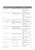
F2040-8

LEK

EB11

EB10

GQ1

PWB1

BP1

QN2

QN3

QN1

BP2

SM1

SM2

LPT

FM01

DH

20S

CH

63H1

F2040-12 /F2040-16

BP1

Tho-R2

BT16

BT14

BT17

BT28

63H1

Tho-R1

Tho-D

Tho-S

Tho-A

LPT

BP2

DH

EB11

20S

QN2

CH

EB10

FM01

GQ1

CT

BE1

SM2

QN1

SM1

QN3

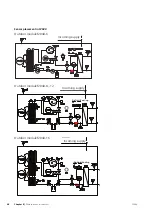
Sensors etc.

Current sensor

BE1 (CT)

High pressure pressostat

BP1 (63H1)

Low pressure transmitter

BP2 (LPT)

Pressure sensor, condenser

BP4

Temperature sensor, heating medium re-
turn line

BT3

Temperature sensor, condenser supply line

BT12

Temperature sensor, hot gas

BT14 (Tho-D)

Temperature sensor, fluid pipe

BT15

Temperature sensor, heat exchanger, 1

BT16 (Tho-R1)

Temperature sensor, suction gas

BT17 (Tho-S)

Temperature sensor, ambient

BT28 (Tho-A)

Compressor heater

EB10 (CH)

Drip tray heater

EB11 (DH)

Condenser

EP2

Fan

GQ1 (FM01)

Compressor

GQ10 (CM)

Drying filter

HS1

Expansion valve

QN1 (EEV)

Expansion valve, heating

QN1 (SM2)

4-way valve

QN2 (20S)

Expansion valve, cooling

QN3 (SM1)

Temperature sensor, heat exchanger, 2

Tho-R2

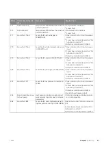
F2040

Chapter 8 |

Disturbances in comfort

46

Summary of Contents for F2040-12

Page 1: ...Installer manual LEK LEK LEK UN F2040 6 8 12 16 Air water heat pump IHB EN 1746 6 231844 ...

Page 2: ......

Page 3: ...4 Pipe connections flex hose 25 Docking alternatives 26 5 Electrical connections 26 General 26 29 Connections 39 6 Commissioning and adjusting 39 Preparations 39 Filling and venting the heating medium sys tem 39 Compressor heater 40 Start up and inspection 41 Readjusting heating medium side 42 Adjustment charge flow 43 7 Control 43 Menu 5 11 1 1 Heat pump EB101 44 8 Disturbances in comfort 44 Trou...

Page 4: ...oushouldobservewhenmaintain ing your installation TIP This symbol indicates tips on how to facilitate using the product Marking Marking The CE mark is obligatory for most products sold in the EU regardless of where they are made CE Classification of enclosure of electro technical equipment IP24 Danger to person or machine Read the User Manual Serial number The serial number for F2040 can be found ...

Page 5: ...mental information The equipment contains R410A a fluorinated green house gas with a GWP value Global Warming Potential of 2088 Do not release R410A into the atmosphere 5 Chapter 1 Important information F2040 ...

Page 6: ...ng medium page 24 System flushed System vented Particle filter Shut off and drain valve Charge flow set Electricity page 26 Fuses property Safety breaker Earth circuit breaker Heating cable type effect Fuse size heating cable F3 Communication cable connected F2040 addressed only when cascade connection Connections Main voltage Phase voltage When installing F2040 6 check that the software version o...

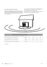
Page 7: ...e F2040 protected from wind against the evaporator Large amounts of condensation water as well as melt water from defrosting may be produced Condensa tion water must be led off to a drain or similar see page 8 Care must be exercised so that the heat pump is not scratched during installation LEK LEK LEK Cirka 1 m LEK LEK LEK Cirka 1 m min 300 mm Min 300 mm Do not place F2040 directly on the lawn or...

Page 8: ... pipe to an appropriate drain it is recommended that the shortest outdoor stretch possible is used The section of the pipe that can be affected by frost must be heated by the heating cable to prevent freezing Route the pipe downward from F2040 The outlet of the condensation water pipe must be at a depth that is frost free or alternatively indoors with reservation for local ordinances and regulatio...

Page 9: ...included Gutter drainage Frostfritt djup LEK Frost proof depth Water seal The outlet of the condensation water pipe must be at frost free depth Route the pipe downward from F2040 The condensation water pipe must have a water seal to prevent air circulation in the pipe Caution If none of the recommended alternatives is used good lead off of condensation water must be assured Supplied components LEK...

Page 10: ...Removing the covers F2040 6 UN F2040 8 LEK F2040 12 LEK F2040 16 LEK F2040 Chapter 2 Delivery and handling 10 ...

Page 11: ...Removing the front panel F2040 6 UN F2040 8 LEK F2040 12 LEK F2040 16 LEK 11 Chapter 2 Delivery and handling F2040 ...

Page 12: ...Removing the side panel F2040 12 LEK F2040 16 LEK DATA F2040 Chapter 2 Delivery and handling 12 ...

Page 13: ... CM 20S SM2 PF3 GQ10 QN1 QM36 QM37 CH EB10 FM01 HS1 BT15 QN2 AA23 BT12 EP2 UB3 TB F PWB1 RF2 RF3 DATA UB3 W1 UB1 UB2 XL1 XL2 DATA PF3 BT28 Tho R1 Tho R1 PF1 BT16 Tho A BT16 13 Chapter 3 The heat pump design F2040 3 The heat pump design ...

Page 14: ...Tho A CM SM2 QN1 CH EB10 GQ10 20S B BT15 QN2 BT12 QN1 BP4 BT3 Q BT28 HS1 UB3 EP2 QM36 QM37 Tho D BT14 F2040 Chapter 3 The heat pump design 14 ...

Page 15: ...2 SM1 FM01 PWB2 PWB3 PWB1 BT12 BT15 BP4 QN2 BT3 PF3 HS1 EP2 GQ10 QN1 BP2 QM36 QM37 BP1 QN3 CH EB10 AA23 X1 F TB BT14 Tho D Tho S BT17 LEK DATA XL2 UB1 UB2 W1 XL1 UB3 LEK DATA PF1 PF3 Tho A BT28 Tho R1 Tho R2 BT16 15 Chapter 3 The heat pump design F2040 ...

Page 16: ... PWB1 PWB2 PWB3 DH UB3 BT3 BP4 PF3 BT15 EP1 EP2 HS1 BP2 BT12 X1 EB11 CM 20S 63H1 LPT SM2 SM1 FM01 CH EB10 AA23 Tho D BT14 BT17 Tho S LEK DATA XL2 UB1 UB2 W1 XL1 UB3 LEK DATA Tho A BT28 PF1 PF3 Tho R1 BT16 Tho R2 F2040 Chapter 3 The heat pump design 16 ...

Page 17: ... DH X1 CM 63H1 CH SM2 SM1 FM01 PWB2 PWB3 PWB1 QN2 20S BT12 TB BP1 PF3 QN3 BP4 BT3 BT15 UB3 GQ10 HS1 QN1 EP2 QM37 QM36 EB11 GQ2 FM02 EP1 F LPT BP2 AA23 Tho D BT14 EB10 Tho S BT17 17 Chapter 3 The heat pump design F2040 ...

Page 18: ...LEK DATA XL2 UB1 UB2 XL1 UB3 W1 LEK DATA PF3 PF1 BT28 Tho A Tho R1 Tho R2 BT16 F2040 Chapter 3 The heat pump design 18 ...

Page 19: ...23 S3 Terminal block KVR AA23 X1 Terminal block communication from indoor module AA23 X4 Communication with TB AA23 X100 Compressor heater EB10 CH Drip tray heater EB11 DH Main fuse compressor unit F Fan GQ1 FM01 Fan GQ2 FM02 Control board PWB1 Inverter board PWB2 Filter board PWB3 EMC filter for inverter RF2 EMC filter for incoming supply RF3 Terminal block incoming supply and commu nication with...

Page 20: ...nnection F2040 6 LEK AA23 AA23 X100 AA23 S3 AA23 X4 AA23 F3 AA23 X1 RF2 UN PWB1 PWB2 PWB3 TB F2040 8 LEK AA23 AA23 X4 AA23 S3 AA23 X100 AA23 X1 AA23 F3 LE K PWB2 PWB1 PWB3 TB F2040 Chapter 3 The heat pump design 20 ...

Page 21: ...rämre el Bakre el LEK EB11 PWB3 PWB1 EB10 AA23 FM01 TB F AA23 F3 AA23 X4 AA23 X1 DH CH GQ1 AA23 S3 AA23 X100 Bakre el LEK LEK PWB2 Capacitor Reactor AF module Diode module 21 Chapter 3 The heat pump design F2040 ...

Page 22: ...l Bakre el LEK PWB3 PWB1 EB10 FM01 AA23 X4 DH CH GQ1 TB AA23 X1 AA23 F3 EB11 F AA23 AA23 S3 FM02 GQ2 AA23 X100 Bakre el LEK LEK PWB2 PWB2 Capacitor Reactor AF module Diode module F2040 Chapter 3 The heat pump design 22 ...

Page 23: ...or heater EB10 CH Drip tray heater EB11 DH Main fuse compressor unit F Fan GQ1 FM01 Fan GQ2 FM02 Control board PWB1 Inverter board PWB2 Filter board PWB3 EMC filter for inverter RF2 EMC filter for incoming supply RF3 Terminal block incoming supply and commu nication with board AA23 TB Designations in component locations according to standard IEC 81346 1 and 81346 2 Designations within brackets acc...

Page 24: ... The heat pump must be vented by the upper connec tion XL1 using the venting nipple on the enclosed flexible hose Install the enclosed particle filter before the inlet i e the lower connection XL2 on F2040 All outdoor pipes must be thermally insulated with at least 19 mm thick pipe insulation Install shutoff and drain valves so that F2040 can be emptied in the event of prolonged power failures The...

Page 25: ...docking options The safety equipment must be installed in accordance with current regulations for all docking options See www nibe eu for more docking options Connecting accessories Instructions for connecting accessories are in the install ation instructions provided for the respective accessory See page 54 for the list of the accessories that can be used with F2040 25 Chapter 4 Pipe connections ...

Page 26: ...ed out in the building disconnect the heat pump Communication cable W2 is inserted from the rear side through UB2 Connect communication cable W2 from terminal block AA23 X4 to the indoor module NOTE Electrical installation and any servicing must be carried out under the supervision of a qual ified electrician Disconnect the current with the circuit breaker before carrying out any ser vicing Electr...

Page 27: ... X4 AA23 S3 AA23 X100 AA23 X1 AA23 F3 LE K PWB2 PWB1 PWB3 TB F2040 12 Främre el Bakre el LEK LEK DH PWB3 CH AA23 FM01 TB F AA23 F3 AA23 X1 PWB1 AA23 X4 AA23 S3 Bakre el LEK LEK PWB2 27 Chapter 5 Electrical connections F2040 ...

Page 28: ...F2040 16 Främre el Bakre el LEK LEK DH PWB3 CH AA23 FM01 TB F AA23 F3 AA23 X1 PWB1 AA23 X4 AA23 S3 Bakre el LEK LEK PWB2 F2040 Chapter 5 Electrical connections 28 ...

Page 29: ...cation and or sensor to external connections cables must not be laid closer than 20 cm to high voltage cables when cable routing Power connection F2040 6 UN Incoming supply Power connection W1 DATA UB3 W1 UB1 UB2 XL1 XL2 29 Chapter 5 Electrical connections F2040 ...

Page 30: ...F2040 8 LEK DATA LEK Incoming supply Power connection W1 XL2 UB1 UB2 W1 XL1 UB3 F2040 12 LEK DATA LEK Incoming supply W1 W1 UB2 UB1 XL1 XL2 UB3 Power connection F2040 Chapter 5 Electrical connections 30 ...

Page 31: ...unication cable W2 provided by in staller to terminal block AA23 X4 and secure with two cable ties see image For connection of accessory KVR 10 heating cable EB14 is connected via cable grommet UB3 see External heat ing cable KVR 10 Accessory on page 33 List of components Cable grommet cascade connection UB1 Cable grommet communication UB2 Cable grommet heating cable EB14 UB3 Cable incoming supply...

Page 32: ... LEK Cables for communication W2 are routed through ferrite beads EMI filters LEK F2040 12 LEK Secure the communication cable W2 here using two cable ties Främre el Bakre el LEK LEK F2040 Chapter 5 Electrical connections 32 ...

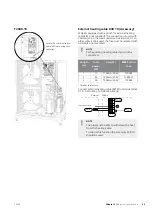
Page 33: ...le one see table NOTE Self regulating heating cables must not be connected NIBE Part no Fuse Fuse F3 Total power W Length m 718085 T100mA 250V 15 1 518900 T250mA 250V 45 3 718086 T500mA 250V 90 6 Fitted at the factory Connect external heating cable EB14 to terminal block X1 4 6 according to following image 5 6 4 2 3 1 External F2040 X1 EB14 External heat cable AA23 F3 NOTE The pipe must be able to...

Page 34: ... trical cable and the heating cable must occur after the gland to the condensation pipe F2040 6 UN Heating cable EB14 Secure the heating cable EB14 here using two cable ties F2040 8 LEK Heating cable EB14 Secure the heating cable EB14 here using two cable ties F2040 12 LEK Heating cable EB14 Secure the heating cable EB14 here using two cable ties F2040 16 LEK Heating cable EB14 Secure the heating ...

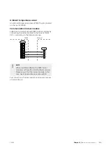
Page 35: ...l block X4 1 3 according to the following image Innemodul X4 F2040 GND GND B B A 15 14 13 A GND B A AA3 1 2 3 4 5 6 External F2040 X4 AA3 NOTE When installing F2040 6 the NIBE indoor module must have the correct software version Please ensure that the indoor module in this case has at least software version v8320 For connection of indoor module see relevant manual on www nibe eu 35 Chapter 5 Elect...

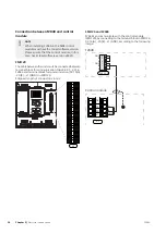
Page 36: ...terminal block for communication X2 19 A 20 B 21 GND in SMO 20 Stripped length of conductor is 6 mm LEK L N 1 1 0 2 3 4 PE 21 20 19 18 17 16 15 14 13 12 11 10 9 8 7 6 5 4 3 2 1 X2 5 6 7 2 1 8 9 13 12 4 3 11 10 19 20 21 14 18 16 17 15 SMO 20 and F2040 F2040 can communicate with the control module SMO 20 by connecting to the terminal block in SMO 20 X2 19 A 20 B 21 GND according to the following ima...

Page 37: ...15 16 17 18 19 10 11 12 13 14 5 6 7 8 9 1 1 N L PE PE 1 2 3 4 5 6 7 8 2 1 2 3 4 5 6 7 8 9 2 3 4 X8 X4 X10 X1 AA5 X4 SMO 40 and more F2040 F2040 one or more can communicate with the control module SMO 40 by connecting to the terminal block in SMO 40 AA5 X4 1 A 2 B 3 GND according to the following image 1 2 3 A B GND 4 5 SMO 40 6 5 4 3 2 1 A B GND A B GND 6 5 4 3 2 1 A B GND A B GND F2040 F2040 F204...

Page 38: ...40 to the control module The default address for F2040 is 1 In a cascade connec tion all F2040 must have a unique address The address is coded in binary S3 3 S3 2 S3 1 Address OFF OFF OFF 1 OFF OFF On 2 OFF On OFF 3 OFF On On 4 On OFF OFF 5 On OFF On 6 On On OFF 7 On On On 8 F2040 Chapter 5 Electrical connections 38 ...

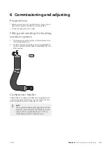
Page 39: ...ing nipple QM20 on the enclosed flexible hose and possibly the circu lation pump QM20 Compressor heater F2040 does not apply to F2040 6 is equipped with a compressor heater that heats the compressor before start up and when the compressor is cold NOTE Thecompressorheatermusthavebeenconnec ted for 6 8 hours before the first start see the section Start up and inspection in the In staller Manual for ...

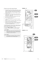
Page 40: ...mmunication cable W2 to the terminal block AA23 X4 7 Restart the indoor module Follow the instructions for Start up and inspection in the installation manual for the indoor module The heat pump starts 30 minutes after the outdoor unit has been powered up and the communication cable W2 has been connected if necessary If scheduledsilent operation is required it must be scheduled in the inner section...

Page 41: ... If bubbling sounds can be heard from the heat pump the circulation pump and radiators the entire system will require further venting When the system is stable correct pressure and all air eliminated the automatic heating control system can be set as re quired 41 Chapter 6 Commissioning and adjusting F2040 ...

Page 42: ...ons for adjusting hot water charging are in the Installer Manual for the relevant indoor module See page 54 for the list of the indoor units and accessories that can be connected to F2040 F2040 Chapter 6 Commissioning and adjusting 42 ...

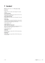
Page 43: ... function is to be activ ated for the heat pump here During active function you can limit the value of the maximum current Setting range 6 32 A Factory setting 32 A Stop temperature compressor Here you can limit the value for set outdoor temperature down to the value the heat pump is to work Setting range 20 2 C Factory setting 20 C blockFreq 1 Select a frequency range within which the heat pump m...

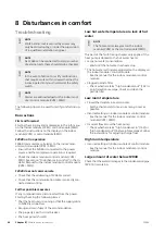
Page 44: ...he power Start by checking the following items That the heat pump is running or that the supply cable to F2040 is connected Group and main fuses of the accommodation The property s earth circuit breaker The heat pump s fuse F Low hot water temperature or a lack of hot water NOTE The hot water is always set on the indoor module VVM or the control module SMO This part of the fault tracing chapter on...

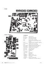
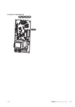
Page 45: ...Sensor placement Connection to board PWB1 F2040 6 UN QN1 BT16 BT14 BT28 EEV Tho R1 Tho D Tho A QN2 EB11 20S DH GQ1 FM01 45 Chapter 8 Disturbances in comfort F2040 ...

Page 46: ...ng medium re turn line BT3 Temperature sensor condenser supply line BT12 Temperature sensor hot gas BT14 Tho D Temperature sensor fluid pipe BT15 Temperature sensor heat exchanger 1 BT16 Tho R1 Temperature sensor suction gas BT17 Tho S Temperature sensor ambient BT28 Tho A Compressor heater EB10 CH Drip tray heater EB11 DH Condenser EP2 Fan GQ1 FM01 Compressor GQ10 CM Drying filter HS1 Expansion v...

Page 47: ...Connection to board AA23 BP4 BT15 BT12 BT3 AA23 S3 47 Chapter 8 Disturbances in comfort F2040 ...

Page 48: ...g supply Outdoor moduleF2040 6 Defrost Cooling Defrost Cooling kW kW kW Incoming supply Outdoor moduleF2040 8 12 Defrost Cooling Defrost Cooling kW kW kW Outdoor moduleF2040 16 Incoming supply F2040 Chapter 8 Disturbances in comfort 48 ...

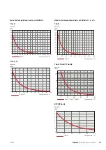
Page 49: ...ratur C Tho A R Resistor Temperature C Data for temperature sensor in F2040 8 12 16 Tho D Motstånd kΩ Temperatur C Tho D 0 20 40 60 80 100 120 140 160 180 200 0 20 40 60 80 100 120 140 160 Resistor Temperature C Tho S Tho R1 Tho R2 Motstånd kΩ Temperatur C Tho S Tho R1 Tho R2 5 0 10 15 0 20 40 60 80 100 Resistor Temperature C BT28 Tho A 0 5 10 15 20 25 30 35 10 20 30 40 50 0 Motstånd kΩ Temperatur...

Page 50: ...0 3 105 74 32 15 3 047 56 20 10 2 976 42 89 5 2 889 33 02 0 2 789 25 61 5 2 673 20 02 10 2 541 15 77 15 2 399 12 51 20 2 245 10 00 25 2 083 8 045 30 1 916 6 514 35 1 752 5 306 40 1 587 4 348 45 1 426 3 583 50 1 278 2 968 55 1 136 2 467 60 1 007 2 068 65 0 891 1 739 70 0 785 1 469 75 0 691 1 246 80 0 607 1 061 85 0 533 0 908 90 0 469 0 779 95 0 414 0 672 100 F2040 Chapter 8 Disturbances in comfort ...

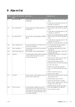
Page 51: ...Set when the heat pump runs the de frosting procedure Not an alarm but an operating status Defrosting in progress 183 Insufficient air circulation or blocked heat exchanger Open circuit or short circuit on input for high pressure switch 63H1 Defective high pressure switch Expansionvalvenotcorrectlyconnected Service valve closed Defective control board in F2040 Low or no flow during heating opera t...

Page 52: ... 261 Can occur when 15V power supply to the inverter PCB is unstable When IPM Intelligent power module displays FO signal Fault Output five times during a 60 minute period Power transistor too hot 262 Incoming power supply interference Service valve closed Insufficient amount of refrigerant Compressor fault Defective circuit board for inverter in F2040 Voltage from the inverter outside the paramet...

Page 53: ...rbances in comfort Defective control board in F2040 Sensor fault hot gas in F2040 Tho D Sensor fault Tho D 279 Open circuit or short circuit on sensor input Sensor does not work see section Dis turbances in comfort Defective control board in F2040 Sensor fault suction gas in F2040 Tho S Sensor fault Tho S 280 Open circuit or short circuit on sensor input Sensor does not work see section Dis turban...

Page 54: ...t no 067 224 SMO 40 Control module Part no 067 225 Indoor module VVM 310 Part no 069 430 VVM 310 With integrated EMK 310 Part no 069 084 VVM320 Copper 3x400 V Part no 069 108 Stainless steel 3x400 V Part no 069 109 Enamel 3x400 V With integrated EMK 300 Part no 069 110 Stainless steel 3x230 V Part no 069 113 Stainless steel 1x230 V Part no 069 111 VVM 500 Part no 069 400 Stand and brackets Ground ...

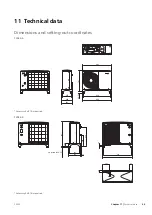
Page 55: ...3 364 307 924 990 741 40 50 Adjustable 40 50 Accessory KVR 10 is required F2040 8 50 Ställbar 40 50 855 400 670 100 365 225 422 965 1035 95 15 90 Ø40 F2040 Adjustable 40 50 Accessory KVR 10 is required 55 Chapter 11 Technical data F2040 11 Technical data ...

Page 56: ...vändning av flera F2040 600 mm 3000 mm 400 mm 600mm Minimalt fritt utrymme Minimalt fritt utrymme Fritt utrymme framför Adjustable 40 50 Accessory KVR 10 is required F2040 16 50 180 Ställbar 40 50 1410 243 512 110 395 265 80 452 1075 1145 108 Ø40 14 85 Adjustable 40 50 Accessory KVR 10 is required F2040 Chapter 11 Technical data 56 ...

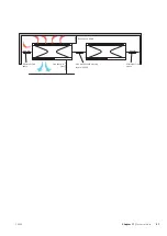
Page 57: ...g av flera F2040 600 mm 3000 mm 400 mm 600mm Minimalt fritt utrymme Minimalt fritt utrymme Fritt utrymme framför Free space behind Min distance when using several F2040 Free space in front Minimum free space Minimum free space 57 Chapter 11 Technical data F2040 ...

Page 58: ...in ground level etc and should therefore only be seen as guide values F2040 adjusts the fan speed depending on the ambient temperature and evaporation temperature 2 m 6 m 10 m 2 m LEK F2040 16 F2040 12 F2040 8 F2040 6 Air water heat pump 61 57 54 50 LW A Sound power level According to EN12102 at 7 45 nominal 47 43 40 36 dB A Sound pressure level at 2 m free standing 37 5 33 5 30 5 26 5 dB A Sound ...

Page 59: ...86 2 61 35 7 C 15 70 5 04 3 12 11 20 3 58 3 12 9 19 2 98 3 08 7 03 2 03 3 45 35 18 C Electrical data 230V 50Hz 230V 2AC 50Hz Rated voltage 25 23 16 15 Arms Max operating current heat pump 24 22 15 14 Arms Max operating current compressor 5 Arms Starting current 2 x 86 86 86 50 W Nominal output fan 25 25 16 16 Arms Fuse1 Refrigerant circuit R410A Type of refrigerant 2 088 GWP refrigerant Twin Rotar...

Page 60: ...35 105 90 66 kg Weight excl packaging Miscellaneous IP 24 Enclosure class 064 108 064 092 064 109 064 206 Part No 1 Specified output is limited with lower fusing SCOP Pdesign SCOP Pdesign F2040 according to EN 14825 16 12 8 6 F2040 SCOP Pdesign SCOP Pdesign SCOP Pdesign SCOP Pdesign 4 48 14 5 4 43 11 5 4 38 8 2 4 8 4 8 SCOP 35 Average cli mate 3 43 14 3 38 10 3 25 7 0 3 46 5 3 SCOP 55 Average cli ...

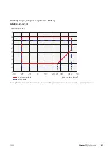
Page 61: ... 7 10 5 0 45 40 43 35 30 25 20 15 10 50 Vattentemperatur C Vattentemperatur C Utomhustemperatur C Water temperature C Outdoor air temperature C Framledning Returledning Framledning Returledning Supply temperature Return temp During shorter time it is allowed to have lower working temperatures on the water side e g during start up 61 Chapter 11 Technical data F2040 ...

Page 62: ...20 30 50 Utomhustemperatur C 35 30 15 25 20 12 7 10 5 0 45 40 43 35 30 25 20 15 10 50 Vattentemperatur C Utomhustemperatur C Water temperature C Outdoor air temperature C Framledning Returledning Framledning Returledning Supply temperature Return temp F2040 Chapter 11 Technical data 62 ...

Page 63: ...kW Utomhustemperatur C F2040 6 Max avgiven effekt 35 45 55 Framledningstemperatur C 35 45 55 Heating output kW Heating output kW Supply temperature C Outdoor temperature C COP F2040 6 0 00 0 50 1 00 1 50 2 00 2 50 3 00 3 50 4 00 25 20 15 10 5 0 5 10 COP Utomhustemperatur C F2040 6 COP Framledningstemperatur C 35 45 55 COP Supply temperature C Outdoor temperature C 63 Chapter 11 Technical data F204...

Page 64: ...iven effekt 35 45 55 Framledningstemperatur C 35 45 55 Heating output kW Outdoor temperature C Heating output kW Supply temperature C COP F2040 8 0 00 1 00 2 00 3 00 4 00 5 00 25 20 15 10 5 0 5 10 15 COP Utomhustemperatur C F2040 8 COP Framledningstemperatur C 35 45 55 COP Supply temperature C Outdoor temperature C F2040 Chapter 11 Technical data 64 ...

Page 65: ... 10 5 0 5 10 15 35 45 55 Framledningstemperatur C 35 45 55 Heating output kW Heating output kW Supply temperature C Outdoor temperature C COP F2040 12 0 00 1 00 2 00 3 00 4 00 5 00 6 00 25 20 15 10 5 0 5 10 15 COP Utomhustemperatur C F2040 12 COP Framledningstemperatur C 35 45 55 COP Supply temperature C Outdoor temperature C 65 Chapter 11 Technical data F2040 ...

Page 66: ...5 10 15 Framledningstemperatur C 35 45 55 35 45 55 Heating output kW Outdoor temperature C Heating output kW Supply temperature C COP F2040 16 0 00 1 00 2 00 3 00 4 00 5 00 6 00 25 20 15 10 5 0 5 10 15 COP Utomhustemperatur C F2040 16 COP Framledningstemperatur C 35 45 55 COP Supply temperature C Outdoor temperature C F2040 Chapter 11 Technical data 66 ...

Page 67: ...ing 20A 0 00 5 00 10 00 15 00 20 00 25 00 25 20 15 10 5 0 5 10 15 Uppvärmningskapacitet kW Utomhustemperatur C Avgiven effekt F2040 16 avsäkring 20A Framledningstemperatur C 35 45 55 Heating output kW Outdoor temperature C Heating output kW Supply temperature C Supplied power F2040 16 fuse rating 20A 0 00 5 00 10 00 15 00 20 00 25 00 25 20 15 10 5 0 5 10 15 Uppvärmningskapacitet kW Utomhustemperat...

Page 68: ... 108 143 116 Seasonal space heating energy efficiency cold climate 235 189 229 185 225 180 252 179 Seasonal space heating energy efficiency warm cli mate 61 57 54 50 dB Sound power level LWA outdoors Data for energy efficiency of the package F2040 16 F2040 12 F2040 8 F2040 6 Model SMO SMO SMO SMO Control module model 35 55 35 55 35 55 35 55 C Temperature application VI Controller class 4 0 Control...

Page 69: ...2 C 1 88 COPd Tj biv kW 4 7 Pdh Tj biv 1 77 COPd Tj TOL kW 4 1 Pdh Tj TOL COPd Tj 15 C if TOL 20 C kW Pdh Tj 15 C if TOL 20 C C 10 TOL Min outdoor air temperature C 7 Tbiv Bivalent temperature COPcyc Cycling interval efficiency kW Pcych Cycling interval capacity C 58 WTOL Max supply temperature 0 99 Cdh Degradation coefficient Additional heat Power consumption in modes other than active mode kW 1 ...

Page 70: ... biv kW 6 6 Pdh Tj biv 1 86 COPd Tj TOL kW 5 9 Pdh Tj TOL COPd Tj 15 C if TOL 20 C kW Pdh Tj 15 C if TOL 20 C C 10 TOL Min outdoor air temperature C 9 Tbiv Bivalent temperature COPcyc Cycling interval efficiency kW Pcych Cycling interval capacity C 58 WTOL Max supply temperature 0 97 Cdh Degradation coefficient Additional heat Power consumption in modes other than active mode kW 1 1 Psup Rated hea...

Page 71: ... biv kW 9 2 Pdh Tj biv 1 92 COPd Tj TOL kW 8 1 Pdh Tj TOL COPd Tj 15 C if TOL 20 C kW Pdh Tj 15 C if TOL 20 C C 10 TOL Min outdoor air temperature C 8 Tbiv Bivalent temperature COPcyc Cycling interval efficiency kW Pcych Cycling interval capacity C 58 WTOL Max supply temperature 0 98 Cdh Degradation coefficient Additional heat Power consumption in modes other than active mode kW 1 9 Psup Rated hea...

Page 72: ...biv kW 12 7 Pdh Tj biv 1 95 COPd Tj TOL kW 11 0 Pdh Tj TOL COPd Tj 15 C if TOL 20 C kW Pdh Tj 15 C if TOL 20 C C 10 TOL Min outdoor air temperature C 8 Tbiv Bivalent temperature COPcyc Cycling interval efficiency kW Pcych Cycling interval capacity C 58 WTOL Max supply temperature 0 98 Cdh Degradation coefficient Additional heat Power consumption in modes other than active mode kW 3 0 Psup Rated he...

Page 73: ...am F2040 6 Part Specification Sheet 051199 0 Page 2 2 Created 2017 08 24 14 20 0 001 LSH 2017 08 24 Production LSH 2017 08 24 230V 230V 2 50Hz WIRING DIAGRAM F2040 6 ELSCHEMA F2040 6 051199 0 73 Chapter 11 Technical data F2040 ...

Page 74: ...F2040 Chapter 11 Technical data 74 ...

Page 75: ...t Specification Sheet 051083 7 Page 2 2 Created 2017 08 16 08 21 0 001 LSH 2017 08 16 Production DLD 2013 02 06 230V 230V 2 50Hz WIRING DIAGRAM F2040 8 ELSCHEMA F2040 8 051083 7 75 Chapter 11 Technical data F2040 ...

Page 76: ...B2 OR GR 1 F P BK BK 4A 2 3 Tho P BP1 63H1 BT14 Tho D BT16 Tho R1 BT17 Tho S BT28 Tho A BP2 LPT 20S QN2 EB10 CH EB11 DH 2 1 1 2 3 4 5 6 AA23 X1 AA23 X100 Matning 230V 50 Hz F2040 Chapter 11 Technical data 76 ...

Page 77: ...F2040 12 77 Chapter 11 Technical data F2040 ...

Page 78: ... WH 1 WH RD BK CNIP Y Tho P BK BK OR CNFAN1 WH BL 7 BR 6 WH 5 4 RD 1 CNH BR BP1 63H1 Two fan unit only Two fan unit only BK BK CNS RD CNR WH CNF BK BL BL EB10 CH BR BR BT14 Tho D BK BK BT16 Tho R1 BK BK CNTH WH BT17 Tho S RD RD BT28 Tho A Y Y 52X1 52X3 EB11 DH BK BK A F MODULE P N2 L1 L L2 1 2 3 SM1 SM2 MS 3 M M CM FM01 20S QN2 CNN1 Y BL BL SV1 BP2 LPT t t t t t t Tho R2 BK BK OR CNFAN2 WH BL 7 BR...

Page 79: ...F2040 16 79 Chapter 11 Technical data F2040 ...

Page 80: ...NB RD 6 BL 4 OR 3 Y 2 WH 1 WH RD BK CNIP Y Tho P BK BK OR CNFAN1 WH BL 7 BR 6 WH 5 4 RD 1 CNH BR BP1 63H1 Two fan unit only BK BK CNS RD CNR WH CNF BK BL BL EB10 CH BR BR BT14 Tho D BK BK BT16 Tho R1 BK BK CNTH WH BT17 Tho S RD RD BT28 Tho A Y Y 52X 52X3 EB11 DH BK BK A F MODULE P N2 L1 L L2 1 2 3 SM1 SM2 MS 3 M M CM FM01 20S QN2 CNN1 Y BL BL SV1 BP2 LPT t t t t t t Tho R2 BK BK OR CNFAN2 WH BL 7 ...

Page 81: ... of the package 68 Information sheet 68 Technical documentation 69 Environmental information 5 External heating cable KVR 10 Accessory 33 F F2040 does not communicate 44 F2040 is not operational 44 Filling and venting the heating medium system 39 G General 24 26 H High room temperature 44 I Important information 4 Environmental information 5 Inspection of the installation 6 Recovery 4 Safety infor...

Page 82: ... locations 13 Electrical components 23 Electrical connection 20 List of components 19 Transport and storage 7 Troubleshooting 44 Basic actions 44 F2040 does not communicate 44 F2040 is not operational 44 High room temperature 44 Large amount of water below F2040 44 Low hot water temperature or no hot water 44 Low room temperature 44 Sensor placement 45 F2040 Chapter 12 Item register 82 ...

Page 83: ...dustrielle RD 28 Rue du Pou du Ciel 01600 Reyrieux Tel 04 74 00 92 92 E mail info nibe fr www nibe fr FR NIBE Energy Systems Ltd 3C Broom Business Park Bridge Way S419QG Chesterfield Tel 44 0 845 095 1200 E mail info nibe co uk www nibe co uk GB NIBE Energietechniek B V Postbus 634 NL 4900 AP Oosterhout Tel 0168 477722 E mail info nibenl nl www nibenl nl NL ABK AS Brobekkveien 80 0582 Oslo Postadr...

Page 84: ...WS name Gemensamt WS version a423 WS release date 2017 09 25 11 38 Publish date 2017 11 24 08 29 NIBE AB Sweden Hannabadsvägen 5 Box 14 SE 285 21 Markaryd info nibe se www nibe eu 231844 ...

Reviews: