


© National Instruments
|
3-3
Replacing the Modular Power Supply
This section describes how to remove, configure, and install the DC power supply shuttle in the
NI PXIe-1082DC chassis. For more information, refer to the
NI PXIe-1082DC Power Supply
Shuttle User Guide
included with your replacement power supply shuttle module.
Caution
Disconnect the power cable prior to replacing the power supply.
Caution
Do not attempt to use a power supply shuttle from another chassis such as
the NI PXI-1042 or NI PXIe-1062Q. Doing so may damage your chassis and the
power supply shuttle.
Before connecting the
power
supply shuttle to a power source, read this section and the
Read
Me First: Safety and Electromagnetic Compatibility
document included with the kit.
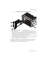
Removal
The NI PXIe-1082DC power supply is a replacement part for the NI PXIe-1082DC chassis.
Before attempting to replace the power supply shuttle, verify that there is adequate clearance
behind the chassis. Disconnect the power cable from the power supply shuttle on the back of the
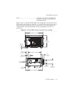
chassis. Identify the eight mounting screws for the NI PXIe-1082DC that attach the power
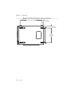
supply shuttle to the chassis. Refer to Figure 1-2,
Rear View of the NI PXIe-1082DC Chassis
for the screw locations. Using a Phillips screwdriver, remove the screws. Pull on the two rear
handles of the power supply shuttle to remove it from the back of the chassis.
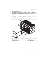
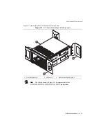
Installation
Ensure that there is no visible damage to the new power supply shuttle. Verify that the housing
and connector on the new power supply shuttle have no foreign material inside. Remove the
protective cap on the PXI_CLK10 connector. Install the new power supply shuttle into the
opening on the rear of the chassis. Replace and tighten the eight screws with a Phillips
screwdriver.
Configuration
The fan-speed selector switch is on the rear panel of the power supply shuttle. Refer to
Figure 1-2,
Rear View of the NI PXIe-1082DC Chassis
, to locate the fan-speed selector. Select
High
for maximum cooling performance (recommended) or
Auto
for quieter operation. Set the
Inhibit Mode switch to the
Default
position.
Connecting to Power Source
Refer to the
section of Chapter 2,


