


©
National Instruments Corp.
7
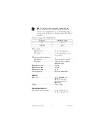
cFP-RLY-423
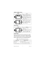
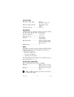
CR (RC or Snubber) Circuits
Varistor Circuit
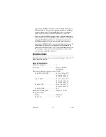
In-Rush Current
The type of load and its in-rush current characteristics, together
with switching frequency, can cause contact welding. For loads
with in-rush current, measure the steady state current and in-rush
current to determine the proper relay. Some typical types of loads
and the in-rush current they create are summarized in Table 3.
Diagram
Notes
Circuit A is suitable for AC or
DC applications, but if used with
AC voltage, impedance of the load
should be smaller than that of the
CR circuit. Do not utilize for timer
loads, as leakage current can cause
faulty operations.
Circuit B is suitable for AC or DC.
If the load is a relay or solenoid,
release times lengthen. Effective
when connected to both contacts,
power supply voltage across the
load is 100 to 200 V.
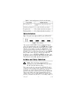
Diagram
Notes
Effective for AC and DC
applications.
Circuit slightly delays release time.
Effective when connected to both
contacts, power supply voltage
across the load is 100 to 200 V.
Table 3.
Typical Load Types and In-Rush Currents
Type of Load
In-Rush Current
Resistive load
Steady-state current
Motor load
5 to 10 times the steady-state current
Incandescent lamp load
10 to 15 times the steady-state current
Load
Load
Load


