6
|
ni.com
|
NI PXIe-5624R Calibration Procedure
Zeroing the Power Sensor
1.
Ensure that the power sensor is not connected to any signals.
2.
Zero the power sensor using the built-in function, according to the power sensor
documentation.
Characterizing Power Splitter Balance
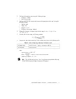
Zero the power sensor as described in the
section prior to starting this
procedure.
This procedure characterizes the balance between the two output terminals of the splitter, where
the second terminal is connected to an attenuator. The power splitter balance is required for the
following procedures:
•
Verifying Absolute Amplitude Accuracy
•
Adjusting Absolute Amplitude Accuracy
The verification and adjustment procedures use test points from 5 MHz to 2.005 GHz in 5 MHz
steps for the splitter balance characterization. Frequencies in which harmonics alias on the
fundamental frequency are excluded from the adjustment procedure. Be careful when applying
splitter balance correction to measurements in the adjustment procedure. Ensure that you are
applying the splitter balance for the correct frequency.
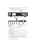
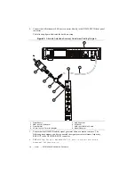
1.
Connect the RF OUT connector of the signal generator to the input port of the power splitter
using an SMA (m)-to-SMA (m) cable.
2.
Connect the 50
Ω
(m) terminator to one of the power splitter output ports. Refer to this port
as splitter output 1.
3.
Connect the other power splitter output to the SMA (f) connector of the 6 dB attenuator
using a 3.5 mm (m)-to-3.5 mm (m) adapter. Refer to the combined power splitter output and
6 dB attenuator as splitter output 2.

