


User Manual: BlueBoard-LPC214X
Revision 1.3
6
2
Get going
2.1
System Requirements
Windows XP
Serial or Parallel port
USB port
2.2
Starting off
2.2.1
Connecting the hardware
After unpacking the BlueBoard connect a DC supply of 7.5V/800mA to the DC jack to power the
board. The BlueBoard can also be powered through USB. To test all the features on the BlueBoard you
would need the following accessories:
1.
USB cable
2.
A VGA cable
3.
DB-9 straight Full and Half modem serial cable
4.
A headphone/speaker to verify the DAC
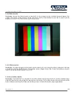
Once you have all these accessories connected to the BlueBoard you can run through a simple
test to verify that all the peripherals are working fine. Please refer to the ‘Hardware Configuration’
section for testing all the peripherals. It is highly recommended that you test all the peripherals as
soon you receive the BlueBoard. The BlueBoard is shipped with the pre-loaded firmware which can
test all the peripherals.
2.2.2
Programming BlueBoard
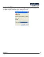
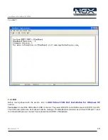
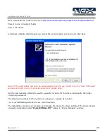
BlueBoard can be programmed through wiggler clone JTAG or through serial port using ‘Flash
Magic’. ‘Flash Magic’ is a freeware windows utility used download the hex file format onto the
BlueBoard. Flash Magic can be downloaded from here
http://www.flashmagictool.com/
. If your PC
does not have a serial port; use a USB to serial converter to download the hex file using the Flash
Magic utility. For programming with JTAG your system should have a parallel port and the supporting
IDE which can communicate to the processor core over JTAG interface. We have successfully tested
BlueBoard with wiggler clone JTAG and CrossWorks IDE. A LINUX utility to download the hex file can
be found here
http://www.pjrc.com/arm/lpc2k_pgm/
.
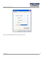
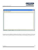
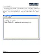
Programming BlueBoard Through ISP.
The BlueBoard can be programmed through ISP in two modes:
1. Auto Mode
2. Manual Mode
1
.
Auto Mode:
To program in Auto mode you need a full serial cable. Set the jumper to pins 2 & 3 of
J26 and connect the full serial cable to UART0 (J5). When BlueBoard is powered ON black boxes will be