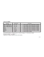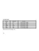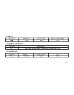
3. When checking in-circuit resistance, be sure the circuit under test has all power removed and all
capacitors fully discharged.
3.4 CONTINUITY TEST
1. Connect the black test lead to the COM jack and the red test lead to the V/Ω jack. (
NOTE:
The
polarity of red lead connection is positive “+”)
2. Set the function switch at
i
position and connect test leads to two points of the circuit under
measurement. If continuity exists (i.e., the resistance is lower than 50Ω), built-in buzzer will
sound.
3.5 TESTING DIODES
1. Connect the black test lead to the COM jack and the red test lead to the V/Ω JACK. (NOTE: The
polarity of the red lead connection is positive “+”)
2. Set the function switch at position.
-13-

