


© 2022 Nexmosphere. All rights reserved. v1.0 / 08-28
All content contained herein is subject to change without prior notice
N ex m o s p h e re
Le H av re 1 3 6
5 6 2 7 SW E i n d h ove n • T h e N e t h e r l a n d s
T
+ 3 1 4 0 2 4 0 7 0 7 0
E
s u p p o r t @ n ex m o s p h e re.c o m
PRODUCT MANUAL | X-DOT I/O INTERFACE
5
Relay
Nexmosphere off ers a Solid State Relay (SSR) which is
compatible with the XDW-I56. The partcode is:
S-RL05231
output max 230VAC/10A
It comes with a 180cm color-coded twisted wire pair
already connected to the screw input terminals of the
relay, and with ferrules for easy connection to the X-Dot
I/O.
The red wire needs to be connected to the Output terminal
of the X-Dot I/O
. The black wire needs to be connected to
the Ground terminal
of the X-Dot I/O
.
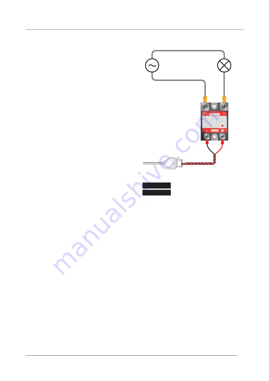
The AC device which is controlled by the relay should
be connected to the OUTPUT terminals
of the relay
as indicated in the schematic on the right. This should
be done by a qualitifed technician according to local
regulations. For correct wiring color codes, please check
local standards.
When the relay is switched ON, the red status LED on the
relay is lit. When the relay is switched off , the red status
LED will be off as well.
Please note the S-RL05231 can only switch AC voltages
as it switches at zero-crossing. It is not possible to switch
DC voltages.
At start-up the output pin on the X-Dot IO will be ON per
default, meaning that the AC device will be ON as well.
X001
AC source
phase
phase /
switch wire
neutral
AC device
(e.g. lamp)
OUTPUT
INPUT
-
+
API commands relay control
Set Relay ON
Set Relay OFF
X001A[1]
X001A[0]


