Copyright © 2009 NEXCOM International Co., Ltd. All Rights Reserved.
5
Chapter 2: Hardware Functionality
NDiS 120 User Manual
C
haPter
2: h
ardware
f
unCtionality
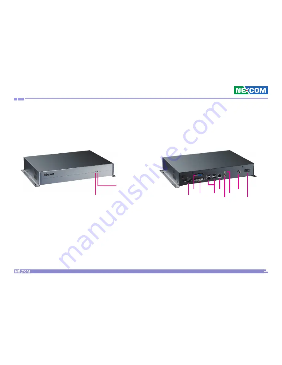
Front Panel
Rear Panel
Power LED
DC 12V
LINE OUT
MIC IN
LAN
USB
VGA
DVI-D
COM
POWER
SWITCH
Storage LED


