background image


Copyright©  2019 NEXCOBOT Co., Ltd. 

26


All Rights Reserved. 


4.2. 

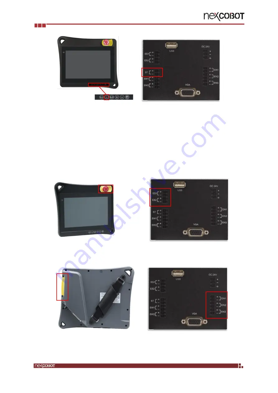
Emergency Stop Button 

The Emergency Stop button locates at the upper-right corner of the TP-100-1 
and  connects  to  ES1  and  ES2  at  the  back  of  the  junction  box.  When  an 
emergency occurs, the Emergency Stop button is pressed to stop all activities, 
the ES1 and ES2’s status will then change from Normal Close (NC) to Normal 
Open (NO). To reset the button, turn it clockwise or counterclockwise to raise 
the button. 


4.3. 

Enabling Switch 


The Enabling switch checks the two-channel mechanical switching elements 
and filter out any asynchronous output signals. It ensures the approval control 

Summary of Contents for TP-100-1

Page 1: ...NEXCOBOT Co Ltd www nexcobot com Teach Pendant TP 100 1 for TM Plug Play User s Manual V1 03 07 17 2020 ...

Page 2: ... of NexCOBOT in advance this document or any part of it shall not be photocopied sold distributed modified published stored or otherwise used To keep this document and its contents correct and complete NexCOBOT reserves the right to change or revise the document at any time without further notification Operating machine or equipment has a certain level of danger It is the user s responsibility to ...

Page 3: ...sion History Rev Description 1 03 Modify Ch2 3 1 02 Modify Ch2 4 Ch4 1 1 01 Modify Ch4 1 1 00 First version release 0 97 Sixth draft release 0 96 Fifth draft release 0 95 Fourth draft release 0 92 Third draft release 0 9 Second draft release 0 8 Draft released ...

Page 4: ...erview of TP 100 1 1 1 2 Handling of TP 100 1 2 TP 100 1 for TM Plug Play 3 2 1 Warning and Caution symbols 3 2 2 Compatibility 3 2 3 TP 100 1 plug play package content 3 2 4 Installation 5 Technical Data 22 3 1 Dimensions 22 3 2 Specification 24 Operation Behaviors 25 4 1 Membrane Keys 25 4 2 Emergency Stop Button 26 4 3 Enabling Switch 26 4 4 Switch Button 28 ...

Page 5: ... PCAP touchscreen technology to reduce the number of buttons and consequently streamlined the operation of the industrial robots 1 1 Overview of TP 100 1 The TP 100 1 is a handheld device that controls robot movements teaches locations and runs robot programs It features an ergonomic housing with safety elements a 10 1 WXGA resolution panel and the Multi Touch PCAP touchscreen technology The contr...

Page 6: ...l Rights Reserved 1 2 Handling of TP 100 1 The TP 100 1 teach pendant is designed to operate in a horizonal landscape format When operating the device make sure to connect all necessary cables from the teach pendant to the host computer ...

Page 7: ...damage WARNING Identifies a potentially hazardous situation which if not avoided will result in minor or moderate injury and might result serious injury death or significant property damage CAUTION Identifies a potentially hazardous situation which if not avoided might result in minor injury moderate injury or property damage 2 2 Compatibility Please use robots shipped with HW SW as table below If...

Page 8: ...3 Seal Washers 1 3 TP 100 Holders 1 4 TP 100 VGA JB 1 Junction box O ring Screws Cap Connectors Content 1 Junction box 1 2 O ring 1 3 M3 12mm screw 4 4 Cap 1 5 Connector 2P 1 6 Connector 3P 1 7 Connector 6P 2 5 TP 100 VGA TM Plug Play Accessory 1 Metal sheet Screws Junction Wires Content 1 Metal Sheet 1 2 Junction Wires 1 3 R632 8mm screws 8 ...

Page 9: ...eserved 2 4 Installation Content of metal sheet NO Metal sheet item Qty 1 Front cover 1 2 Right side cover 1 3 Left side cover 1 4 Bottom cover 1 5 R6 32 8mm screw 8 Step 1 Fix Junction box with front cover Note these 3 screws are in TP 100 VGA JB ...

Page 10: ...NEXCOBOT Co Ltd 6 All Rights Reserved Step 2 Fix front cover with right side cover and left side cover to TM robot cabinet Remove the rubber from the controller cabinet Before remove the rubber After remove the rubber ...

Page 11: ...s Reserved Note these 4 screws are in TP 100 VGA TM Plug Play Accessory M4x0 7 8mm CAUTION DO NOT power on the system before finishing the installation and wiring DO NOT remove the wiring during power on which may result in damage to the system ...

Page 12: ...1 3 Signal power wire 1 4 Signal wire 1 5 Ground wire 1 2 Pin definition of Junction Wires Wire Junction box side TM controller side HDMI to VGA VGA port HDMI port USB USB port USB port Signal power wire red 24V red ST white DI13 white black GND black ST green GND green Signal wire ES2 red SAFE red ES2 white SI0 1 white ES1 black SAFE black ES1 blue SI0 2 blue ...

Page 13: ...SAFE purple EN1 green SI3 2 green Ground wire yellow green yellow green 3 Connector direction of Junction Wires DANGER DO NOT wrongly connected the safety devices into wrong safety inputs or non safety inputs ports on the TM control box Make sure the safety devices are correctly connected to the corresponded safety input ports Junction Box Side TM Controller Side ...

Page 14: ...e switch is lightly pressed and held in the middle position EN1 EN2 EN2 EN3 EN3 Emergency Stop Button ES1 Emergency stop button are switches that quickly and reliably provide two channel signal for switching machines and systems to a safe state in an emergency ES1 ES2 ES2 Switch Button SW1 A general purpose button which provide two channel signal and can be used as power switch of system SW1 SW2 S...

Page 15: ...Reserved Please note that the Robot Cable should be wired first before Junction Wires to prevent potential interference CAUTION If the wiring does not follow this approach the radius of curvature will be too small which may damage the robot cable ...

Page 16: ...Copyright 2019 NEXCOBOT Co Ltd 12 All Rights Reserved Step 4 Fix bottom cover with right side cover and left side cover Note these 4 screws are in TP 100 VGA TM Plug Play Accessory M4x0 7 8mm ...

Page 17: ...military specifications are used to connect with the junction box The connector consists of a plug male pin and a receptacle female socket Follow the steps below to connect the junction box with the teach pendent 2 Ring terminal of grounding cable 1 Fix the grounding cable with the metal sheet 1 Seal Washers 3 Screw Location for fixing grounding cable ...

Page 18: ...clockwise until you cannot turn it anymore 3 Push the second green ring toward the junction box and repeat steps 1 and 2 until the junction box and plug are tightly connected Note DO NOT twist the black ring to tighten the connection 2 Align the notch of the plug with the latch of the receptacle ...

Page 19: ... while the Robot Controller is power on The label on the cable is showing waring symbol to users do not hot plug while robot controller is power on 1 Turn the first green ring on the plug counterclockwise to disconnect the junction box 2 Pull the second green ring opposite from the junction box once and repeat steps 1 and 2 until the junction box and plug are disconnected ...

Page 20: ...served Connect extension wire to TP 100 1 Step 6 Installation check CAUTION Before booting up the robot system make sure that all of the parts with electrics like teach pendant or safeguard devices have been correctly connected and securely fastened ...

Page 21: ...td 17 All Rights Reserved Step 7 Set up with TMflow 1 User should first log in and Get Control of the Robot Note TP 100 1 is only available with HW3 2 control box 2 Click Input Display Device in the System page and select Pendant ...

Page 22: ...Copyright 2019 NEXCOBOT Co Ltd 18 All Rights Reserved 3 Click I O Setup in the Setting page User Defined I O input 13 Stick Stop Button and Save ...

Page 23: ...Copyright 2019 NEXCOBOT Co Ltd 19 All Rights Reserved 4 Click Safety in the Setting page select Enable Enabling Device in the Safety IO Setting and Save ...

Page 24: ...ow is fully set up Now you can test the pendant with the six buttons on it Test with error log button is shown below DANGER Make sure the pendant settings are properly set then start to use otherwise the system may be malfunction or lose of function and cause dangerous risks ...

Page 25: ...wer on single press Shutdown long press M A Mode Switch Button Toggle Manual Auto Mode Switch For details refer to our TMflow User Manual Enabling Device The 3 position enabling switch For details refer to Section 3 3 3 SF5 Pendant Enabling Device Play Pause Button Play Pause Project single press Stop Button Press this button to stop any project Button Adjust project speed single press under Manua...

Page 26: ...Copyright 2019 NEXCOBOT Co Ltd 22 All Rights Reserved Technical Data 3 1 Dimensions TP 100 1 ...

Page 27: ...Copyright 2019 NEXCOBOT Co Ltd 23 All Rights Reserved TP 100 VGA JB Front Back Stud M3 4 Unit mm ...

Page 28: ...24Vdc max Safety Elements Emergency stop button 2 NC channels B10d 130 000 Contact function latching Reset by rotating 3 position Deadman switch 3 channels 2 NO 1 NC B10d 100 000 Mechanical Dimension 297 3 x 257 2 x 57 2 mm 78 5mm including E stop button Weight without external control cable TP 100 1 1 5Kg TP 100 1 IP protection class Full IP65 Junction Box module and install on TM control box IP ...

Page 29: ...d at the lower right of the teach pendant Please note that the M A key is only functioning after users log in TMflow The stop key on membrane provides a hard wired signal and connects to ST and ST at the back of junction box When the stop button is pressed the ST and ST status will then change from Normal Open NO to Normal Close NC ...

Page 30: ... When an emergency occurs the Emergency Stop button is pressed to stop all activities the ES1 and ES2 s status will then change from Normal Close NC to Normal Open NO To reset the button turn it clockwise or counterclockwise to raise the button 4 3 Enabling Switch The Enabling switch checks the two channel mechanical switching elements and filter out any asynchronous output signals It ensures the ...

Page 31: ...teach pendant are synchronized at all time 6 0 Travel mm 3 0 0 Position Pin Position 1 Position 2 Position 3 When pressing the switch EN1 Open Close Open EN1 EN2 Open Close Open EN2 EN3 Close Close Open EN3 When releasing the switch EN1 Open Open Open EN1 EN2 Open Open Open EN2 EN3 Close Close Open EN3 ...

Page 32: ... at the back of the junction box When the switch button is pressed the SW1 status will change from Normal Close NC to Normal Open NO and SW2 status will change from Normal Open NO to Normal Close NC Pin Contact When pressing the switch SW1 Open SW1 SW2 Close SW2 When releasing the switch SW1 Close SW1 SW2 Open SW2 ...

Reviews: