


Copyright © 2023 NexCOBOT Co., Ltd. All Rights Reserved.
8
NEX 813 User Manual
Chapter 2: Jumpers and Connectors
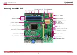
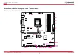
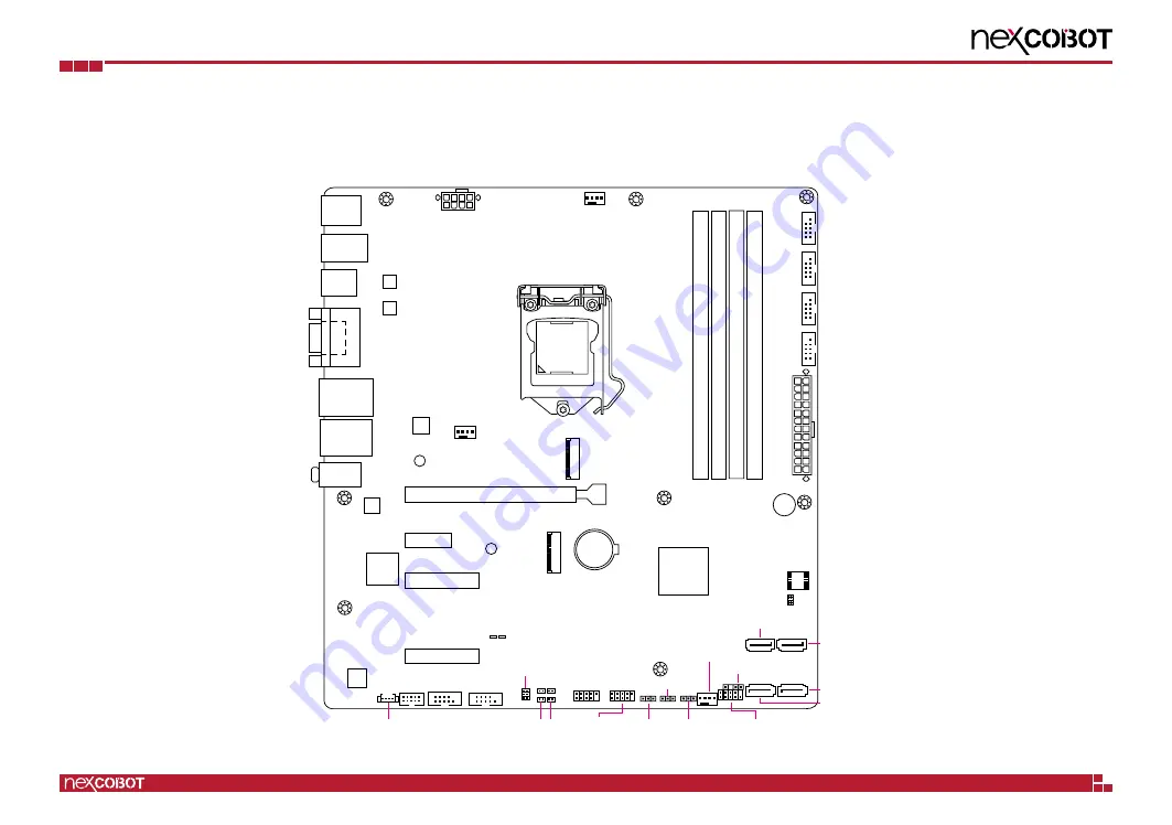
Locations of the Jumpers and Connectors
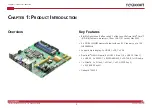
The figure below shows the location of the jumpers and connectors.
PCIEX16_1
PCIEX1_1
PCIEX4_1
PCIEX4_2
F_PANEL
CLRTC1
DIS_ME
ATX_AT
CHASSIS
USB1112
EATX_
PWR1
CHA_FAN1
CHA_FAN2
BATTERY
Super
I/O
ALC
887
Intel
I211AT
Intel
PHY I219LM
ASM
1442K
DP
LGA1151
Intel
®
Q370
DDR4 DIMM_A1* (64bit, 288-pin module)
DDR4 DIMM_A2 (64bit, 288-pin module)
DDR4 DIMM_B1* (64bit, 288-pin module)
DDR4 DIMM_B2 (64bit, 288-pin module)
SATA6G_3
SATA6G_4
SATA6G_1
M2_TYPE_M1
M2_TYPE_E1
SPI_1
SATA6G_2
BUZZER1
AUDIO1
LAN2_USB3_910
KBMS
_USB31
_12
USB31_3456
LAN1_USB3_78
128Mb
BIOS
EATX_PWR2
CPU_FAN1
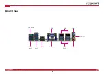
VGA
COM3
COM4
COM2 COM1
COM5
COM6
DIO1
AMP_CON1
M2_TYPE_M1
M2_TYPE_E1
2280
2230
COM1_V1
J1 J4
J3 J2
LED_5VSB
LED_5V
HDMI_12
ASM
1442K
USB13


