4.
Alignment and Measurement
4.2.4.
Zero Scan Range
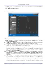
The ZERO SCAN function ("SETUP"
→
Scan Range
→
Zero) stops the delay at the zero position, i.e.
the pulses in both interferometer arms travel the same, xed, not periodically changing distance.
On the measurement screen the signal becomes a at line. Then SHG intensity is displayed as a
function of time. Now the signal is similar to an oscilloscope. It is thereby possible to observe
amplitude modulations and thus it is sometimes easier to adjust the autocorrelator to maximize
the ACF.
4.2.5.
Further Alignment Optimization: Beam Shutters
A good beam alignment may be veri ed using the internal beam shutters. To do so the
Pulse
Scout2
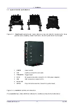
has two shutters activated by push buttons on top of the device (see Figure 3.3 on page 18). First
close either of the shutters by pushing the corresponding button down. The background signal
should go down to half intensity (provided you have set the "BEAM DISTANCE" screw to the collinear
position). Repeat this step with the other shutter where the signal drop should be the same. If both
shutters are closed simultaneously, the signal should go down to almost zero (only the background
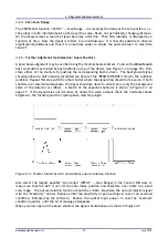
noise of the detector is visible). A sketch of the expected behavior is shown in Figure 4.7 on
page 27. If the signal does not decrease by nearly the same amount check the horizontal beam
alignment, the focusing and the crystal phase-matching angle.
Figure 4.7.: Shutter functions with and without autocorrelation function
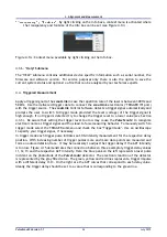
Also select the largest possible "scan range" (SETUP
→
Scan Range) in the Control Software to
make sure that the ACF is not off the zero delay position and therefore not visible in a small
scan range. The autocorrelation function should be visible. Maximize the autocorrelation signal
with the "Sensitivity" arrows. Reduce either the sensitivity or gain settings in case of an overload
condition, indicated by the software. Reduce the optical input power, in case the "overload"
condition persists, until the error message disappears.
When you now operate the beam shutters the signal should behave as shown in Figure 4.7.
Pulse
Scout2 Version 1.1
27
July 2015

