


Features and Specifications
19
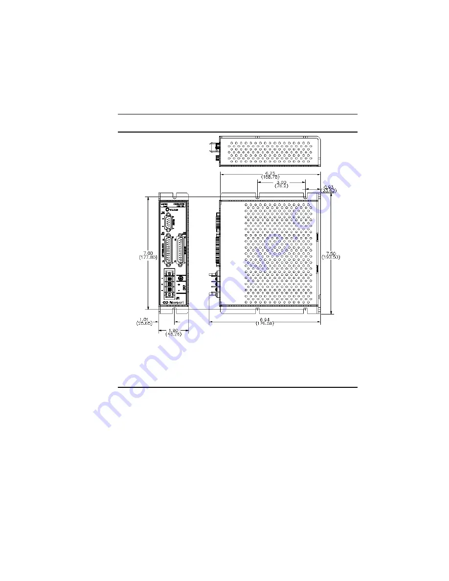
3.3 Outside
Dimensions
Figure 4:
Outline Dimensions for CDR-DCB and CDR-STEP Amplifiers.
3.4
Features and Specifications
3.4.1 System
Features
•
Windows software configurable motor drive settings.
•
Operates from DC power with optical isolation between /Enable
and /Amp OK signals and power stages.
•
Drives Newport positioners with motors up to 4 Amps.
Summary of Contents for CDR-DCB
Page 1: ...C Drive Brush DC Servo and Stepper Amplifier Model CDR STEP Model CDR DCB User s Manual...
Page 4: ...iv Preface Declaration Of Conformity CDR DCB STEP 2002...
Page 16: ...16 Safety Precautions This page is intentionally left blank...
Page 42: ...42 Function This page is intentionally left blank...
Page 49: ...System Overview 49 DRIVER 5V DRIVER 5V Figure 25 Cable CD Connections to Terminal Blocks...
Page 58: ...58 Notes Notes...


