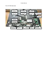
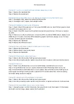
background image

X

N Service Manual 

Problem #1: 

Can’t turn on machine (Power indicator always stay on red) 

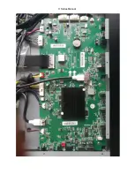
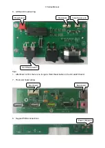
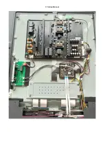
Step 1: Replace the mainboard first. 

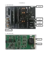
Step 2: Replace the powerboard. 

Problem #2: Dim screen (After turn on, the display get image but is very faint hard to see)

Step 1: If backlight is ON, replace the optical bonding module. 

Step 2: If backlight is OFF, replace the backlight module. 
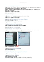
Problem #3: 

Android can’t pick up the OPS signal 

Step 1: Check if the OPS is powered on

.


If

 not, press POWER button on the OPS front panel


to check


if the OPS can be powered on or not. 

Step 2: Check if the OPS can work with another known-working touchscreen

.


I

it does not,

 replace


the OPS.  

Step 3: If there 

are

 no other touchscreen

s

, connect the OPS via external HDMI cable to 

display

’s rear


HDMI IN port

.


I

it works, 

check the OPS installed the graphic card driver

s

 properly or not

. I

it does 

not

 work

, install the graphic card driver

s

.

Step 4: Replace the mainboard.  

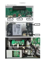
Step 5: Replace the OPS dock board. 

Problem #4: No power (Power indicator is blank even no red colour) 

Step 1: Replace the Powerboard 

Step 2: Replace the AC relay control board. 

Step 3: Replace the Mainboard. 

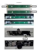
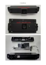
Problem #5: Partial touch or dead touch area 

Step 1: Refer to Part 

B

 to test the FlatFrog touch panel signal.

Step 2: According to testing result

s, 

replace

 one


pcba sensor 

or 

replace a w

hole set 

of pcba 

sensor

s

.

Problem #6: No touch 

Step 1: Check if only Windows has no touch or both Windows and Android have no touch.

Step 2: If only Windows has no touch, replace mainboard and OPS docking board one by one. 

Step 3: If both Windows and Android have no touch, please refer to Part 

B

 to test the FlatFrog touch


panel signal

.


A

ccording to testing result

s, 

replace the TP control board at first

.


I

f

 still

 not working,


send back testing result

for analysis.

Problem #7: Ghost touch or the calibration is inaccurate 

Step 1: Refer to Part 

B

 to test the FlatFrog touch panel signal.

Step 2: 

According to testing results, replace one pcba sensor or replace a whole set of pcba sensors

.

Problem #8: No image (Black screen) even no faint display 

Step 1: 

Unplug t

he power cord for 30

 seconds,

 then 

plug it back in


and

 check again

.


I

f it 

the display


start

with 

a normal image

, please replace the Powerboard.

Summary of Contents for TRUTOUCH VN Series

Page 1: ...X Series Service Manual...

Page 2: ...is essential that all components be replaced with authorized components recommended in this manual to prevent shock fire or any other hazards 3 Please do not modify the original mechanical or electri...

Page 3: ...art A PCBA Overviews OPS Dock board Mainboard Power board TempSensor T con board Audio board Wifi module Front port board Keypad board Power_IR board AC board TP control board R Micphone L Micphone To...

Page 4: ...1 Mainboard wiring AC board Front port board FF control board Powerboard T Con board T Con board Front port board Power_IR board 5 6SHDNHU OPS docking board Audio board OPS docking board Top Bottom C...

Page 5: ...X Series Manual...

Page 6: ...X Series Manual 2 Powerboard wiring 3 Audio board wiring OC panel OPS docking board FF control board Mainboard AC switch board Mainboard Mic R...

Page 7: ...X Series Manual 4 OPS docking board wiring 5 Wifi module wiring Mainboard Mainboard Powreboard Mainboard Antenna...

Page 8: ...wiring Tips 1 After March 2018 there is no longer a Hard Reset button in the AC switch board 7 Front port board wiring 8 Keypad PCBA connections Powerboard Mainboard TempSensor pcb Hard Reset button M...

Page 9: ...X Series Manual 9 Power_IR board wiring 10 TempSensor PCBA wiring AC switch board Keypad board Mainboard...

Page 10: ...X Series Manual 11 FlatFrog Touch Panel Control board wiring 12 T CON board wiring Powerboard Mainboard Mainboard TP PCBA TP PCBA Mainboard Mainboard...

Page 11: ...X Series Manual...

Page 12: ...X Series Manual 13 Micphone pcba L R wiring 14 Camera module wiring Mainboard L Microphone Mainboard R Microphone...

Page 13: ...X Series Manual...

Page 14: ...e files to the root folder of the USB drive as shown in the following images Step 2 Turn off the display and connect the USB drive to the below front USB port Step 3 Turn on the display and the firmwa...

Page 15: ...X Series Manual Step 5 On the first boot up after the firmware upgrade it will stay on the X Series splash logo for about 3 minutes Step 6 Go to settings menu to check the firmware version is correct...

Page 16: ...Problem 5 Partial touch or dead touch area Problem 6 No touch Problem 7 Ghost touch or the calibration is inaccurate Problem 8 No image Black screen even no faint display Problem 9 Noise in the image...

Page 17: ...nk even no red colour Step 1 Replace the Powerboard Step 2 Replace the AC relay control board Step 3 Replace the Mainboard Problem 5 Partial touch or dead touch area Step 1 Refer to Part B to test the...

Page 18: ...nto homepage Step 1 Reload FW for mainboard Step 2 If it does not work replace Mainboard Problem 12 Broken sound or sound popping Step 1 It should be a speaker issue replace the speaker Problem 13 No...

Page 19: ...XN Service Manual Thank you for reading For more info please contact the manufacturer or authorized agent...

Reviews: