


8
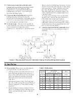
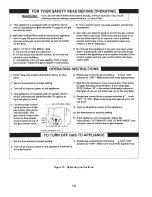
Figure 6: Pilot and Gas Piping, Continuous
Ignition (Standing Pilot)
Figure 7: Pilot and Gas Piping, Intermittent
Ignition (EI)
V. Venting
A.
Install
vent system
in accordance with local building
codes; or local authority having jurisdiction; or
National Fuel Gas Code
, ANSI Z223.1/NFPA 54, Part 7,
Venting of Equipment. Install any of the following for
this Classic CG-A Series Category I, draft hood
equipped appliance:
1. Type B or Type L gas vent. Install in accordance
with listing and manufacturer's instructions.
2. Masonry or metal chimney. Build and install in
accordance with local building codes; or local
authority having jurisdiction; or
Standard for
Chimneys, Fireplaces, Vents, and Solid Fuel
Burning Appliances
, ANSI/NFPA 211.
Masonry chimney must be lined with approved clay
flue lining or listed chimney lining system except as
provided in ANSI Z223.1/NFPA 54, Paragraph
7.5.4(a):
Exception: Where permitted by the
authority having jurisdiction, existing chimneys
shall be permitted to have their use continued when
an appliance is replaced by an appliance of similar
type, input rating, and efficiency.
3. Single wall metal vent. Allowed by ANSI Z223.1/
NFPA 54 under very restrictive conditions.
B.
Inspect chimney
and remove any obstructions or
restrictions. Clean chimney if previously used for solid
or liquid fuel-burning appliances or fireplaces.
R
E
G
N
A
D
g
n
i
l
l
a
t
s
n
i
e
r
o
f
e
b
y
e
n
m
i
h
c
g
n
i
t
s
i
x
e
t
c
e
p
s
n
I
d
e
t
a
r
o
f
r
e
p
e
c
a
l
p
e
r
r
o
n
a
e
l
c
o
t
e
r
u
l
i
a
F
.
r
e
l
i
o
b
r
o
y
r
u
j
n
i
e
r
e
v
e
s
e
s
u
a
c
l
l
i
w
g
n
i
n
i
l
e
l
i
t
r
o
e
p
i
p
.
h
t
a
e
d
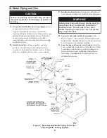
C.
Install Draft Hood
without modification on outlet of flue
collector. See Figure 1. Secure with sheet metal screws.
G
N
I
N
R
A
W
y
n
a
e
c
a
l
p
r
o
d
o
o
h
t
f
a
r
d
r
e
l
i
o
b
r
e
t
l
a
t
o
n
o
D
e
h
t
n
i
r
e
p
m
a
d
d
e
v
o
r
p
p
a
-
n
o
n
r
o
n
o
i
t
c
u
r
t
s
b
o
e
g
a
l
l
i
p
s
s
a
g
e
u
l
F
.
m
e
t
s
y
s
t
n
e
v
r
o
g
n
i
h
c
e
e
r
b
e
m
o
c
e
b
l
l
i
w
n
o
i
t
a
c
i
f
i
t
r
e
c
L
T
E
.
r
u
c
c
o
n
a
c
.
d
i
o
v
D.
Install Blocked Vent Switch.
The Blocked Vent Switch
Assembly shipped taped to top of boiler includes power
cord and switch attached to mounting bracket.
1. Untape Blocked Vent Switch Assembly from top of
boiler. Uncoil power cord.
2. Position mounting bracket onto lower edge of Draft
Hood skirt. Locate center tooth (with #10 sheet
metal screw) on outside and other two teeth inside
Draft Hood skirt. See Figure 8.
Summary of Contents for CG-A 30
Page 16: ...16 Figure 15 Operating Instructions ...
Page 17: ...17 Figure 16 Lighting Instructions ...
Page 20: ...20 ...
Page 21: ...21 ...


