background image

Engine - Engine and crankcase

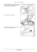
85. Remove the six bolts

(1)

from the stub shaft cover.

Remove the cover.

RCPH10CCH077BAB

61

86. Thread a M12 bolt

(1)

into the end of the stub shaft.

RCPH10CCH922AAB

62

87. Pull out the stub shaft to disconnect the engine drive.

RCPH10CCH923AAB

63

47533593 01/10/2013

10.1 [10.001] / 21

Summary of Contents for T8.275

Page 1: ...AL T8 275 T8 300 T8 330 T8 360 T8 390 T8 420 ContinuouslyVariableTransmission CVT Tractor PIN ZCRC02586 and above Printed in U S A Copyright 2013 CNH America LLC All Rights Reserved New Holland is a registered trademark of CNH America LLC Racine Wisconsin 53404 U S A ...

Page 2: ...uously Variable Transmission CVT 21 1 21 505 Continuously Variable Transmission CVT external controls 21 2 21 507 Continuously Variable Transmission CVT internal components 21 3 21 506 Continuously Variable Transmission CVT lubrication system 21 4 Four Wheel Drive 4WD system 23 23 202 Electro hydraulic control 23 1 23 314 Drive shaft 23 2 Front axle system 25 25 100 Powered front axle 25 1 25 102 ...

Page 3: ...33 2 33 220 Trailer brake hydraulic control 33 3 33 224 Trailer brake pneumatic control 33 4 Hydraulic systems 35 35 000 Hydraulic systems 35 1 35 102 Pump control valves 35 2 35 106 Variable displacement pump 35 3 35 114 Three point hitch control valve 35 4 35 124 Three point hitch hydraulic adjustment 35 5 35 204 Remote control valves 35 6 35 300 Reservoir cooler and filters 35 7 35 304 Combinat...

Page 4: ... 5 55 050 Heating Ventilation and Air Conditioning HVAC control system 55 6 55 051 Cab Heating Ventilation and Air Conditioning HVAC controls 55 7 55 100 Harnesses and connectors 55 8 55 130 Rear three point hitch electronic control system 55 9 55 201 Engine starting system 55 10 55 301 Alternator 55 11 55 302 Battery 55 12 55 404 External lighting 55 13 55 405 External lighting switches and relay...

Page 5: ... bodywork and decals 90 90 100 Engine hood and panels 90 1 90 102 Engine shields hood latches and trims 90 2 90 118 Protections and footboards 90 3 90 124 Pneumatically adjusted operator seat 90 4 90 150 Cab 90 5 90 151 Cab interior 90 6 90 160 Cab interior trim and panels 90 7 47533593 01 10 2013 Find manuals at https best manuals com ...

Page 6: ...47533593 01 10 2013 Find manuals at https best manuals com ...

Page 7: ...INTRODUCTION 47533593 01 10 2013 1 Find manuals at https best manuals com ...

Page 8: ...6 NA T8 420 ZCRC02586 NA Safety rules Do Not Operate tag 7 T8 275 ZCRC02586 NA T8 300 ZCRC02586 NA T8 330 ZCRC02586 NA T8 360 ZCRC02586 NA T8 390 ZCRC02586 NA T8 420 ZCRC02586 NA Safety rules Ecology and the environment 8 T8 275 ZCRC02586 NA T8 300 ZCRC02586 NA T8 330 ZCRC02586 NA T8 360 ZCRC02586 NA T8 390 ZCRC02586 NA T8 420 ZCRC02586 NA Torque Minimum tightening torques for normal assembly 9 T8...

Page 9: ...gional or local dealers reject any responsibility for damages caused by parts and or components not approved by the manu facturer including those used for the servicing or repair of the product manufactured or marketed by the manufacturer In any case no warranty is given or attributed on the product manufactured or marketed by the manufacturer in case of damages caused by parts and or components n...

Page 10: ...with WARNING is ORANGE CAUTION used with the safety alert symbol indicates a hazardous situation which if not avoided could result in minor or moderate injury The color associated with CAUTION is YELLOW FAILURE TO FOLLOW DANGER WARNING AND CAUTION MESSAGES COULD RESULT IN DEATH OR SERIOUS INJURY Machine safety NOTICE Notice indicates a situation which if not avoided could result in machine or prop...

Page 11: ...points indicated in this manual Incorrect towing procedures can cause accidents When you tow a disabled machine follow the procedure in this manual Use only rigid tow bars Stop the engine remove the key and relieve pressure before you connect or disconnect fluid lines Stop the engine and remove the key before you connect or disconnect electrical connections Scalding can result from incorrect remov...

Page 12: ...8 300 ZCRC02586 NA T8 330 ZCRC02586 NA T8 360 ZCRC02586 NA T8 390 ZCRC02586 NA T8 420 ZCRC02586 NA Personal Protective Equipment PPE Wear Personal Protective Equipment PPE such as hard hat eye protection heavy gloves hearing protection pro tective clothing etc 47533593 01 10 2013 6 ...

Page 13: ...A T8 300 ZCRC02586 NA T8 330 ZCRC02586 NA T8 360 ZCRC02586 NA T8 390 ZCRC02586 NA T8 420 ZCRC02586 NA Do Not Operate tag Before you start servicing the machine attach a Do Not Operate warning tag to the machine in an area that will be visible 47533593 01 10 2013 7 ...

Page 14: ...contact with all fuels oils acids solvents etc Most of them contain substances that may be harmful to your health Modern oils contain additives Do not burn contaminated fuels and or waste oils in ordinary heating systems Avoid spillage when draining off used engine coolant mixtures engine gearbox and hydraulic oils brake fluids etc Do not mix drained brake fluids or fuels with lubricants Store the...

Page 15: ... in M8 18 N m 163 lb in 25 N m 217 lb in 26 N m 234 lb in 35 N m 311 lb in 17 N m 151 lb in 24 N m 212 lb in M10 37 N m 27 lb ft 49 N m 36 lb ft 52 N m 38 lb ft 70 N m 51 lb ft 33 N m 25 lb ft 48 N m 35 lb ft M12 64 N m 47 lb ft 85 N m 63 lb ft 91 N m 67 lb ft 121 N m 90 lb ft 58 N m 43 lb ft 83 N m 61 lb ft M16 158 N m 116 lb ft 210 N m 155 lb ft 225 N m 166 lb ft 301 N m 222 lb ft 143 N m 106 lb...

Page 16: ...9 N m 343 lb in 18 N m 163 lb in 27 N m 240 lb in M10 40 N m 30 lb ft 54 N m 40 lb ft 57 N m 42 lb ft 77 N m 56 lb ft 37 N m 27 lb ft 53 N m 39 lb ft M12 70 N m 52 lb ft 93 N m 69 lb ft 100 N m 74 lb ft 134 N m 98 lb ft 63 N m 47 lb ft 91 N m 67 lb ft M16 174 N m 128 lb ft 231 N m 171 lb ft 248 N m 183 lb ft 331 N m 244 lb ft 158 N m 116 lb ft 226 N m 167 lb ft M20 350 N m 259 lb ft 467 N m 345 lb...

Page 17: ...ft 7 16 48 N m 36 lb ft 65 N m 48 lb ft 68 N m 50 lb ft 91 N m 67 lb ft 50 N m 37 lb ft 71 N m 53 lb ft 1 2 74 N m 54 lb ft 98 N m 73 lb ft 104 N m 77 lb ft 139 N m 103 lb ft 76 N m 56 lb ft 108 N m 80 lb ft 9 16 107 N m 79 lb ft 142 N m 105 lb ft 150 N m 111 lb ft 201 N m 148 lb ft 111 N m 82 lb ft 156 N m 115 lb ft 5 8 147 N m 108 lb ft 196 N m 145 lb ft 208 N m 153 lb ft 277 N m 204 lb ft 153 N...

Page 18: ...85 lb ft 153 N m 113 lb ft 74 N m 55 lb ft 104 N m 77 lb ft 9 16 117 N m 86 lb ft 156 N m 115 lb ft 165 N m 122 lb ft 221 N m 163 lb ft 106 N m 78 lb ft 157 N m 116 lb ft 5 8 162 N m 119 lb ft 216 N m 159 lb ft 228 N m 168 lb ft 304 N m 225 lb ft 147 N m 108 lb ft 207 N m 153 lb ft 3 4 287 N m 212 lb ft 383 N m 282 lb ft 405 N m 299 lb ft 541 N m 399 lb ft 261 N m 193 lb ft 369 N m 272 lb ft 7 8 4...

Page 19: ...8 4 Grade Identification Grade Corner Marking Method 1 Flats Marking Method 2 Clock Marking Method 3 Grade A No Notches No Mark No Marks Grade B One Circumferential Notch Letter B Three Marks Grade C Two Circumferential Notches Letter C Six Marks 47533593 01 10 2013 13 ...

Page 20: ... hub length standard axle Differential 11 8 l 12 5 US qt A 21 6 UK pt Planetary each 1 4 l 3 US pt 2 5 UK pt 4 Pin 180 mm 7 in hub length heavy duty axle Differential 11 8 l 12 5 US qt 20 8 UK pt Planetary each 3 3 l 7 US pt 5 8 UK pt 4 pin 250 mm 10 in hub length heavy duty class 5 axle Differential 15 l 15 8 US qt 26 4 UK pt Planetary each 6 l 12 7 US pt 10 5 UK pt New Holland 4 5 fixed front ax...

Page 21: ...l 2 and count the number of pins 3 on the wheel end to determine axle type for your tractor RCPH11CCH074AAB 1 RCIL08CCH001EAA 2 Axle oil viscosity temperature usage recommendation NEW HOLLAND AMBRA HYPOIDE 140 NEW HOLLAND AMBRA HYPOIDE 90 NEW HOLLAND AMBRA HYPOIDE SSL GEAR OIL 47533593 01 10 2013 15 ...

Page 22: ...chine RCIL11CCH008EAA 1 1 Type Permissible towable mass 2 EEC number 7 Unbraked towable mass 3 Product identification number 8 Independently brakes towable mass 4 Total permissible mass 9 Inertia braked towable mass 5 Permissible front axle load 6 Permissible rear axle load 10 Towable mass fitted with an assisted braking system hydraulic or pneumatic Model Serial number NOTE Located on right hand ...

Page 23: ...o the left hand side of the engine block just below the oil cooler RAIL12TR02140AA 4 Transmission serial number NOTE Located on the right hand side of the transmission to the left of the main hydraulic filter RAIL12TR01410AA 5 Powershift transmission RAIL12TR02191AA 6 Auto Command 47533593 01 10 2013 17 ...

Page 24: ...NEW HOLLAND4 5 fixed 4 75 fixed 4 75 saddle suspended 5 0 fixed and 5 0 saddle suspended front axle housings example shown Located on the rear right hand side of the Dana heavy duty fixed 5 0 fixed and 5 0 fixed saddle suspended axles RAIL12TR02142AA 7 47533593 01 10 2013 18 ...

Page 25: ...SERVICE MANUAL Engine T8 275 ZCRC02586 T8 300 ZCRC02586 T8 330 ZCRC02586 T8 360 ZCRC02586 T8 390 ZCRC02586 T8 420 ZCRC02586 47533593 01 10 2013 10 ...

Page 26: ...er heads 10 2 10 114 Pump drives 10 3 10 202 Air cleaners and lines 10 4 10 216 Fuel tanks 10 5 10 310 Aftercooler 10 6 10 400 Engine cooling system 10 7 10 414 Fan and drive 10 8 10 500 Selective Catalytic Reduction SCR exhaust treatment 10 9 47533593 01 10 2013 10 ...

Page 27: ...Engine 10 Engine and crankcase 001 T8 275 ZCRC02586 T8 300 ZCRC02586 T8 330 ZCRC02586 T8 360 ZCRC02586 T8 390 ZCRC02586 T8 420 ZCRC02586 47533593 01 10 2013 10 1 10 001 1 ...

Page 28: ...s Engine 10 Engine and crankcase 001 SERVICE Engine Remove 3 T8 275 T8 300 T8 330 T8 360 T8 390 T8 420 ZCRC02586 Install 24 T8 275 T8 300 T8 330 T8 360 T8 390 T8 420 ZCRC02586 47533593 01 10 2013 10 1 10 001 2 ...

Page 29: ...0 ATTENTION For tractors equipped with front PTO hitch refer to steps 80 95 for additional disassembly instructions NOTE Clean all fittings before disconnecting NOTE Cap or plug all lines and ports when disconnecting hydraulic components 1 Remove the nuts 1 securing the condenser fuel cooler RCPH10CCH054BAB 1 2 Disconnect the refrigerant hose from the receiver dryer 1 and the condenser outlet hose...

Page 30: ...g and remove the fuel hoses at the cooler RCPH10CCH897AAB 5 6 Loosen the hydraulic hose fittings 1 at the oil cooler Remove the hoses Carefully remove the cooler and set aside NOTE Be prepared to collect some hydraulic fluid RCPH10CCH898AAB 6 7 Remove the bolts 1 securing the right hose bracket 2 RCPH10CCH899AAB 7 47533593 01 10 2013 10 1 10 001 4 ...

Page 31: ...ooler outlet tube 11 Remove the clamp 4 at the elbow to the intake man ifold 12 Remove the tube assembly 5 and set aside RCPH10CCH056BAB 8 13 Remove and discard the intake elbow O ring seal 1 RCPH10CCH903AAB 9 14 Loosen the clamps 1 and disconnect the engine coolant outlet 2 and inlet hoses 3 RCPH10CCH902AAB 10 47533593 01 10 2013 10 1 10 001 5 ...

Page 32: ...r assembly RCPH10CCH057BAB 11 16 On the right hand side at the A C compressor discon nect the four harness connectors 1 Remove the A C line clamp 2 RCPH10CCH059BAB 12 17 Disconnect the high pressure 1 and suction 2 A C lines from the compressor RCPH10CCH060BAB 13 47533593 01 10 2013 10 1 10 001 6 ...

Page 33: ...4AAB 14 19 Disconnect the harness connector 1 for the fan drive RCPH10CCH905AAB 15 20 Remove the nut 1 and disengage the alternator out put cable 2 RCPH10CCH907AAB 16 21 Disconnect the harness connector 1 for the engine grid heater and the power supply cable 2 RCPH10CCH062BAB 17 47533593 01 10 2013 10 1 10 001 7 ...

Page 34: ...or inlet line 5 RCPH10CCH061BAB 18 25 At the front of the engine disengage the clamp 1 and remove the blowby recirculation tube 2 and set aside RCPH10CCH807AAB 19 26 Remove the attaching bolts 1 and remove the ex haust shield 2 and set aside RCPH10CCH906AAB 20 27 Disconnect the harness 1 and supply and return hose connections 2 at the SCR dosing valve 3 RCPH10CCH908AAB 21 47533593 01 10 2013 10 1 ...

Page 35: ...t Set the bracket 2 aside RCPH10CCH909AAB 22 29 Open the insulation blanket 1 and remove the ex haust pipe clamp 2 RCPH10CCH910AAB 23 30 Remove the support clamp bolt 1 and the lower pipe clamp 2 Remove the pipe 3 and set aside RCPH10CCH063BAB 24 47533593 01 10 2013 10 1 10 001 9 ...

Page 36: ... intake air tube and set aside RCPH10CCH808AAB 26 35 Loosen the clamp 1 Remove the turbo inlet elbow 2 and set aside RCPH10CCH809AAB 27 36 Locate the tank heater control 1 for the SCR system above the engine 37 Disengage the connector locking wire 2 and discon nect the inlet connector 3 38 Repeat for the outlet connector 39 Disconnect the harness connector 4 RCPH10CCH911AAB 28 47533593 01 10 2013 ...

Page 37: ...nector 2 for the 12 V auxiliary post 1 43 Open the protective cover 3 remove the attaching nuts and disconnect the power cable into 4 and from 5 the fuse block 44 Disconnect the power relay harness connector 6 RCPH10CCH070BAB 30 45 Remove the bolt 1 securing the hose clamp 2 for the DEF AdBlue tank heater return line 46 Remove the bolts 3 securing the bracket 4 to the hood support RCPH10CCH071BAB ...

Page 38: ...0CCH794AAB 32 48 Remove the front bracket attaching bolts 1 Remove the bracket 2 and set aside RCPH10CCH069BAB 33 49 Disengage the clamp and disconnect the hose 1 to the coolant recovery bottle Remove the bracket 2 bolts 3 Set bottle bracket aside RCPH10CCH914AAB 34 47533593 01 10 2013 10 1 10 001 12 ...

Page 39: ...ttaching bolts 4 RCPH10CCH072BAB 35 52 Remove the bolts 1 securing the rear hose tube bracket 2 Place the hose tube assembly along side the tractor RCPH10CCH915AAB 36 53 Disconnect the connectors 1 between the engine and transmission harnesses RCPH10CCH916AAB 37 54 At the cab disconnect the A C high 1 and low pres sure 2 tube fittings RCPH10CCH920AAB 38 47533593 01 10 2013 10 1 10 001 13 ...

Page 40: ...peat for the battery positive 2 and alternator out put 3 cables 58 Remove the bolt and disengage the engine ground cable 4 RCPH10CCH919AAB 40 59 Remove the plug 1 and screw 2 and remove the starter solenoid wire 3 Reinstall the screw RCPH10CCH818AAB 41 60 At the left front cab mount remove the bolt and dis connect the ground connector 1 RCPH10CCH921AAB 42 47533593 01 10 2013 10 1 10 001 14 ...

Page 41: ...t 1 Remove the bracket support bolts 2 from the left shown and right sides RCPH10CCH918AAB 43 62 Remove the assembly and set aside RCPH10CCH075BAB 44 63 Remove the cooling package assembly iso mount nut and bolt Repeat for the opposite side RCPH10CCH913AAB 45 47533593 01 10 2013 10 1 10 001 15 ...

Page 42: ...he cooling package RCPH10CCH068BAB 46 65 Remove the bolt securing the harness clamp 1 66 Remove the six nuts and washers 2 securing the fan drive to the pulley 67 Remove the fan and drive assembly and set aside RCPH10CCH073BAB 47 68 Remove the bolts 1 and cover for the drop box drive shaft Set the cover aside RCPH10CCH813AAB 48 47533593 01 10 2013 10 1 10 001 16 ...

Page 43: ...CCH817AAB 49 70 Remove the bolts 1 from the plate 2 for the right rear engine mount RCPH10CCH925AAB 50 71 Remove the front bolt and washer 1 securing the hood support 72 Remove the bolts and washers from the plate 2 for the left rear engine mount Remove the plate and set aside RCPH10CCH080BAB 51 47533593 01 10 2013 10 1 10 001 17 ...

Page 44: ...ed RCPH10CCH084BAB 52 74 Remove the right rear engine mount Inspect for wear and or damage Replace as required Repeat for the left side RCPH07CCH166AAB 53 75 Remove the four bolts 1 securing the brackets 2 for the front engine mount 76 Remove the bolt 3 securing the front engine mount 4 77 Inspect mount for wear and or damage Replace as required RCPH10CCH833AAB 54 47533593 01 10 2013 10 1 10 001 1...

Page 45: ...PH10CCH076BAB 55 Tractors equipped with front PTO hitch 80 Tag or mark the front PTO hitch hoses and disconnect from each side of the support bracket NOTE Be prepared to collect some hydraulic fluid RCPH11CCH009AAB 56 81 Remove the bolt 1 securing the tube clamps 2 Re move the clamps and set aside Move tube hose as sembly off to the side RCPH11CCH006AAB 57 47533593 01 10 2013 10 1 10 001 19 ...

Page 46: ...oler for the front PTO RCPH11CCH002BAB 58 83 Remove the bolts 1 securing the cooler brackets 2 Remove the cooler and set aside RCPH11CCH003BAB 59 84 Remove the four bolts 1 from the drive shaft 2 be tween the drop box and output box RCPH10CCH651AAB 60 47533593 01 10 2013 10 1 10 001 20 ...

Page 47: ...ts 1 from the stub shaft cover Remove the cover RCPH10CCH077BAB 61 86 Thread a M12 bolt 1 into the end of the stub shaft RCPH10CCH922AAB 62 87 Pull out the stub shaft to disconnect the engine drive RCPH10CCH923AAB 63 47533593 01 10 2013 10 1 10 001 21 ...

Page 48: ... and straps RCPH10CCH078BAB 64 89 Remove the four socket head bolts 1 securing the left hand bracket to the drop box 90 Loosen the four bolts 2 that attach the bracket to the engine RCPH11CCH005AAB 65 91 Remove the four socket head bolts 1 that secure the right hand bracket 2 to the drop box RCPH11CCH001BAB 66 47533593 01 10 2013 10 1 10 001 22 ...

Page 49: ...hand left brackets 1 far enough out ward so the dowel pins 2 clear the drop box 3 94 Carefully raise and move the drop box out of the for ward engine compartment RCPH10CCH079BAB 68 95 Remove the bolts 1 the plate 2 for the front engine mount RCPH10CCH926AAB 69 Next operation Engine Install 10 001 47533593 01 10 2013 10 1 10 001 23 ...

Page 50: ...g brackets 1 2 Torque the four mounting bolts 2 to 101 113 N m 75 83 lb ft 3 Torque the ISO mount support bolt nut 3 to 160 220 N m 118 162 lb ft RCPH10CCH833AAB 1 4 Install the right shown and left rear engine ISO mounts RCPH07CCH166AAB 2 5 Properly support the engine Raise and move the en gine into the front support frame RCPH10CCH084BAB 3 47533593 01 10 2013 10 1 10 001 24 ...

Page 51: ...rear engine mount with the bolts 2 removed earlier 10 Torque the bolts to 125 150 N m 92 2 110 6 lb ft RCPH10CCH925AAB 5 11 Clean any rust corrosion and or paint from the mount ing location 1 for the grounding cable at the left rear engine mounting bracket 2 Also clean the bolt and grounding cable 12 Install the bolts 3 removed earlier and torque to 125 150 N m 92 111 lb ft 13 Install the hood sup...

Page 52: ... lb ft RCPH10CCH817AAB 7 17 Install the engine output drive shaft cover 1 Use the bolts 2 removed earlier to secure the cover to the flywheel housing RCPH10CCH813AAB 8 Tractors equipped with front PTO hitch 18 If removed install the right reversing gear housing support bracket 1 RCPH10CCH079BAB 9 19 Install the four mounting bolts and washers 1 that were removed earlier Do not tighten at this time...

Page 53: ...ing a bolt 2 into the end of the shaft and pulling forward approximately one half way RCPH10CCH923AAB 12 22 Properly support the drop box housing and carefully place into position between the support brackets RCPH10CCH078BAB 13 23 Using the four socket head bolts 1 removed earlier secure the left support bracket 2 to the drop box housing 24 Torque the bolts to 235 N m 173 lb ft RCPH11CCH005AAB 14 ...

Page 54: ... bolts for the right and left support bracket to the engine to 30 40 N m 22 30 lb ft Check the shaft movement If the shaft moves in and out freely continue to tighten the bolts while checking shaft movement Tighten to a final torque of 122 N m 90 lb ft If the shaft binds loosen the mounting bolts for the support brackets Adjust the brackets retorque the bolts to 30 40 N m 22 30 lb ft and check sha...

Page 55: ...ve shaft for the output box on the engine drop box 32 Use the four socket head bolts removed earlier to se cure the drive shaft 33 Torque the bolts to 42 N m 31 0 lb ft Lubricate 3 the drive shaft as required RCPH10CCH651AAB 19 34 If removed install the front PTO oil cooler 1 Secure with the bolts and nuts removed earlier 2 RCPH11CCH003BAB 20 47533593 01 10 2013 10 1 10 001 29 ...

Page 56: ...d two wrench method to tighten the hoses RCPH11CCH002BAB 21 36 Install new O ring seals in the fittings and reconnect the front hitch supply and return hoses RCPH11CCH009AAB 22 37 Reinstall the tube clamp 1 and secure with the bolt 2 removed earlier RCPH11CCH006AAB 23 47533593 01 10 2013 10 1 10 001 30 ...

Page 57: ...ive harness clamp 3 to the support bracket RCPH10CCH073BAB 24 41 Properly support the cooling package and carefully lift into place NOTICE Use caution when lowering the cooling package into place Do not allow the fan blade to strike the radiator or charge air cooler RCPH10CCH068BAB 25 42 Install the cooling package ISO mount bolt 1 Repeat for the opposite side RCPH10CCH912AAB 26 47533593 01 10 201...

Page 58: ...p of the engine RCPH10CCH075BAB 28 45 Using the four bolts 1 remove earlier secure the rear of the bracket to the hood support 46 Secure the harness clamp 2 to the hood support RCPH10CCH918AAB 29 47 At the right front cam mount bracket 1 clean any paint rust or corrosion from the ground connector lo cation 2 48 Use the bolt 3 removed earlier to secure the ground wire RCPH10CCH921AAB 30 47533593 01...

Page 59: ...re with the jumper stud 4 Install the protective cover 5 52 Connect the engine to front frame grounding strap 6 and secure with the starter mounting bolt RCPH10CCH919AAB 32 53 Connect the exhaust pipe assembly 1 to the tur bocharger outlet flange Do not tighten the clamp 2 at this time RCPH10CCH917AAB 33 54 Install new O ring seals and connect the air condition ing high 1 and low 2 pressure fittin...

Page 60: ...gine block RCPH10CCH915AAB 36 57 Connect the cab heater supply 1 and return 2 tubes 58 Connect the coolant from the deaeration tank tube 3 Install and tighten the hose clamp 59 Using the bolts 4 removed earlier secure the support bracket to the engine block RCPH10CCH072BAB 37 60 Using the bolts 1 removed earlier secure the coolant recovery bottle bracket assembly 2 to the engine block 61 Connect t...

Page 61: ...e bracket 1 Using the bolts 2 removed earlier secure the front of the bracket RCPH10CCH069BAB 40 64 Using the bolts 1 removed earlier secure the rear of the bracket 2 to the hood support 65 Using the bolt 2 removed earlier secure the hose clamp 3 for the DEF AdBlue supply tank heater re turn RCPH10CCH071BAB 41 47533593 01 10 2013 10 1 10 001 35 ...

Page 62: ... the protective cover 5 RCPH10CCH070BAB 42 70 Connect the lower portion of the air intake tube assem bly 1 to the air cleaner outlet hose Do not tighten the hose clamp 2 at this time RCPH10CCH064BAB 43 71 Using the bolts 1 removed earlier secure the upper potion of the air intake tube assembly 2 to the sup port bracket 3 72 Connect the air intake elbow 4 to the tube assembly Do not tighten the hos...

Page 63: ...y and return fittings 1 Tighten the fittings using the two hand two wrench method 75 Install the fuel cooler supply and return hoses 2 and secure with the hose clamps RCPH10CCH066BAB 46 76 At the DEF AdBlue supply module 1 engage the in let connector 2 and secure by pushing the locking wire 3 inward 77 Repeat for the outlet not shown 78 Connect the module harness connector 4 RCPH10CCH911AAB 47 475...

Page 64: ...and lower 2 exhaust pipes 82 Tighten the exhaust pipe clamp 3 83 Secure the insulating blanket 4 84 Check and tighten all exhaust pipe clamps RCPH10CCH910AAB 49 85 Using the bolts 1 removed earlier attach the exhaust shield mounting bracket 2 RCPH10CCH909AAB 50 86 At the selective catalytic reduction doser 1 connect the harness 2 and the supply and return hoses 3 RCPH10CCH908AAB 51 47533593 01 10 ...

Page 65: ...ect the following hoses and pipes Fuel supply hose 1 Fuel return hose 2 Engine blow by pipe 3 If equipped the air compressor inlet pipe 4 Engage and tighten all hose clamps as required RCPH10CCH061BAB 53 89 At the front of the engine install the engine blow by pipe 1 and engage the hose clamp 2 RCPH10CCH807AAB 54 47533593 01 10 2013 10 1 10 001 39 ...

Page 66: ...91 Connect the heater controller harness 2 RCPH10CCH062BAB 55 92 Install the alternator output cable 1 and secure with the nut removed earlier RCPH10CCH907AAB 56 93 Connect the fan drive harness connectors 1 RCPH10CCH905AAB 57 94 If equipped connect the suspended axle harness con nectors 1 RCPH10CCH904AAB 58 47533593 01 10 2013 10 1 10 001 40 ...

Page 67: ...e to the compressor and or tubes do not over tighten the fittings RCPH10CCH060BAB 59 96 Install the air conditioning line support clamp 1 and secure with the bolt removed earlier 97 Connect the four harness connectors as shown 2 RCPH10CCH059BAB 60 98 Using the bolts 1 removed earlier secure the over head line support assembly to the cooling package RCPH10CCH057BAB 61 47533593 01 10 2013 10 1 10 00...

Page 68: ...pipe RCPH10CCH903AAB 63 102 Install the intake air pipe 1 103 Tighten flange clamp 2 and 3 104 Install the turbocharger outlet to air cooler inlet pipe 4 105 Tighten the flange clamp at the turbocharger not shown 106 Tighten hose clamp 5 107 Install new O ring seals Using the two hand two wrench method tighten the hydraulic oil cooler sup ply and return hoses 6 RCPH10CCH056BAB 64 108 Using the bol...

Page 69: ...nnect the fuel into and from fuel cooler hoses 1 and engage the hose clamps 2 RCPH10CCH897AAB 67 112 Position the air conditioning condenser 1 over it s mounting studs 2 Install the nylock nuts and tighten until there is minimal up down movement and it still opens freely 113 Install new O ring seal and using the two hand two wrench method tighten the condenser outlet fitting 3 114 Install new O ri...

Page 70: ...perly latched RCPH10CCH894AAB 69 Next operation Engine cooling system Filling 10 400 Next operation Air conditioning Evacuate 50 200 Next operation Air conditioning Charging 50 200 Next operation Hood Install 90 100 Next operation Battery Connect 55 302 47533593 01 10 2013 10 1 10 001 44 ...

Page 71: ...Engine 10 Engine and crankcase 001 Engine Install 24 T8 275 T8 300 T8 330 T8 360 T8 390 T8 420 ZCRC02586 Engine Remove 3 T8 275 T8 300 T8 330 T8 360 T8 390 T8 420 ZCRC02586 47533593 01 10 2013 10 1 10 001 45 ...

Page 72: ...47533593 01 10 2013 10 1 10 001 46 ...

Page 73: ...Engine 10 Cylinder heads 101 T8 275 ZCRC02586 T8 300 ZCRC02586 T8 330 ZCRC02586 T8 360 ZCRC02586 T8 390 ZCRC02586 T8 420 ZCRC02586 47533593 01 10 2013 10 2 10 101 1 ...

Page 74: ... heads 101 SERVICE Valve cover Remove Over head components 3 T8 275 T8 300 T8 330 T8 360 T8 390 T8 420 ZCRC02586 Install Over head components 6 T8 275 T8 300 T8 330 T8 360 T8 390 T8 420 ZCRC02586 47533593 01 10 2013 10 2 10 101 2 ...

Page 75: ...ngine coolant system 2 Disengage the hose clamp 1 and disconnect the en gine blow by tube 2 at the engine air intake to tur bocharger 3 If equipped disconnect the air inlet pipe 3 for the air compressor RCPH10CCH061BAB 1 4 Remove the exhaust shield 1 and set aside RCPH10CCH906AAB 2 5 Loosen the hose clamp 1 and disconnect the air inlet elbow 2 at the turbocharger RCPH10CCH809AAB 3 47533593 01 10 2...

Page 76: ... pipe 2 9 Remove and set aside the intake air pipe assembly RCPH10CCH064BAB 5 10 Loosen the hose clamp 1 and disconnect the deaer ation tank to engine fill hose 2 RCPH11CCH970AAB 6 11 Remove the support clamp 1 for the deaeration tank to engine fill tube 12 Remove the three bolts 2 from the tube support bracket and remove the bracket NOTE Remove the bracket for access to an engine valve cover bolt...

Page 77: ...e the bracket and set aside RCPH11CCH972AAB 8 14 Remove the 18 bolts from the valve cover Remove the valve cover and set aside RCPH11CCH973AAB 9 15 Refer to the engine manual for proper valve adjust ment Next operation Valve cover Install Over head components 10 101 47533593 01 10 2013 10 2 10 101 5 ...

Page 78: ... valve cover tighten the bolts in a crossing pattern 2 4 Torque all bolts to 7 10 N m 5 2 7 4 lb ft RCPH11CCH973AAB 1 5 Install the turbocharger support bracket 1 6 Torque bolts 2 to 60 70 N m 44 52 lb ft 7 Torque mounting bolts 3 that were removed earlier to 38 45 N m 28 33 lb ft RCPH11CCH972AAB 2 8 Using the three bolts 1 removed earlier secure the tube support bracket 2 to the engine block 9 Pl...

Page 79: ... the bolts 1 removed earlier secure the air in take tube 2 to the support bracket 13 Connect the air intake elbow 3 to the pipe 14 Do not tighten the hose clamp 4 at this time RCPH10CCH808AAB 6 15 Connect the air inlet elbow 3 to the turbocharger NOTICE Loose hose clamps could allow dust to enter the turbocharge and engine causing premature wear NOTE Tighten all intake air hose clamps at this time...

Page 80: ...ke air tube 1 to the engine intake air tube Using the two hand two wrench method tighten the fitting 2 18 Connect the engine blow by hose 3 to the air inlet pipe to the turbocharger and engage the hose clamp RCPH10CCH061BAB 9 Next operation Fill the coolant system Refer to Engine cooling system Filling 10 400 Next operation Battery Connect 55 302 47533593 01 10 2013 10 2 10 101 8 ...

Page 81: ...This as a preview PDF file from best manuals com Download full PDF manual at best manuals com ...

Reviews: