3. ATTACHMENT DIMENSIONS
3-4
3.1.2
BOOM MAINTENANCE STANDARD
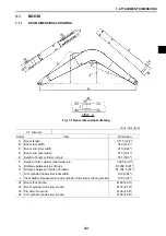
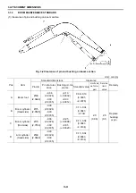
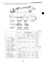
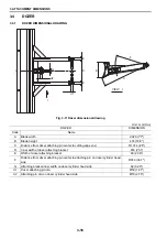
(1) Clearance of pin and bushing on boom section
Fig. 3-2 Clearance of pin and bushing on boom section
Unit : mm (in)
Pos.
Item
Standard dimensions
Clearance
Remedy
Pin dia.
Pin dia. toler-
ance
Bushing i.d. tol-
erance
Standard value
Limit val-
ue for re-
pair
Service
limit
value
A
Boom foot
Ø60
(2.3622)
–0.06
(-0.0024)
-0.09
(-0.0035)
+0.10
(+0.0039)
+0.03
(+0.0012)
0.09~0.19
(0.0035
~0.0075)
2.0
(0.08)
2.5
(0.1)
Replace
bushing
or pin
B
Boom cylinder
(Head side)
Ø75
(2.9528)
-0.06
(-0.0024)
-0.09
(-0.0035)
+0.25
(+0.0098)
+0.05
(+0.0020)
0.11~0.34
(0.0043
~0.134)
C
Boom cylinder
(Rod side)
Ø70
(2.7559)
-0.06
(-0.0024)
-0.09
(-0.0035)
0.11~0.34
(0.0043
~0.0134)
D
Arm cylinder
(Head side)
Ø60
(2.3622)
-0.06
(-0.0024)
-0.09
(-0.0035)
0.11~0.34
(0.0043
~0.0134)
Summary of Contents for E70SR
Page 2: ...Find manuals at https best manuals com ...
Page 5: ...0 1 SAFETY PRECAUTIONS Find manuals at https best manuals com ...
Page 12: ...1 OUTLINE 1 2 ...
Page 18: ...1 OUTLINE 1 8 MEMO ...
Page 20: ...2 SPECIFICATIONS 2 2 ...
Page 34: ...2 SPECIFICATIONS 2 16 MEMO ...
Page 36: ...3 ATTACHMENT DIMENSIONS 3 2 ...
Page 51: ...This as a preview PDF file from best manuals com Download full PDF manual at best manuals com ...

