INTRODUCTION
Change fluid
Replace
Cleaning
Drain fluid
Grease
Test
Check
Maintenance action
Page no.
Auxiliary battery connections
x
Battery removal and installation
Work lights
ELECTRICAL SYSTEM
Fuses and relays
47907870 06/10/2015
23
Page 1: ... PIN NFDC16000 and above SERVICE MANUAL 1650M Tier 2 Crawler Dozer PIN NCDC16500 and above PIN NDDC16500 and above PIN NEDC16000 and above PIN NFDC16000 and above Part number 47907870 2nd edition English October 2015 Replaces part number 47619921 2015 CNH Industrial America LLC All Rights Reserved Part number 47907870 ...
Page 2: ... PAT Blade Extra Long Track XLT Non regulated NDDC16500 1650M Power Angle Tilt PAT Blade Extra Long Track XLT Non regulated NEDC16000 1650M Power Angle Tilt PAT Blade Extra Long Track XLT Non regulated NFDC16000 1650M Power Angle Tilt PAT Blade Low Ground Pressure LGP Non regulated NCDC16500 1650M Power Angle Tilt PAT Blade Low Ground Pressure LGP Non regulated NDDC16500 1650M Power Angle Tilt PAT...
Page 3: ...50M Bulldozer BD Blade Extra Long Track XLT Non regulated NDDC16500 Latin America F4HFA613M E001 1650M Bulldozer BD Blade Extra Long Track XLT Non regulated NEDC16000 Middle East Africa F4HFA613M E001 1650M Bulldozer BD Blade Extra Long Track XLT Non regulated NEDC16000 Latin America F4HFA613M E001 1650M Bulldozer BD Blade Extra Long Track XLT Non regulated NEDC16000 Asia Pacific F4HFA613M E001 16...
Page 4: ...alia New Zealand F4HFA613M E001 1650M Power Angle Tilt PAT Blade Extra Long Track XLT Non regulated NEDC16000 Asia Pacific F4HFA613M E001 1650M Power Angle Tilt PAT Blade Extra Long Track XLT Non regulated NEDC16000 Australia New Zealand F4HFA613M E001 1650M Power Angle Tilt PAT Blade Extra Long Track XLT Non regulated NEDC16000 Latin America F4HFA613M E001 1650M Power Angle Tilt PAT Blade Extra L...
Page 5: ...ddle East Africa F4HFA613M E001 1650M Power Angle Tilt PAT Blade Low Ground Pressure LGP Non regulated NEDC16000 Middle East Africa F4HFA613M E001 1650M Power Angle Tilt PAT Blade Low Ground Pressure LGP Non regulated NEDC16000 Australia New Zealand F4HFA613M E001 1650M Power Angle Tilt PAT Blade Low Ground Pressure LGP Non regulated NEDC16000 Latin America F4HFA613M E001 1650M Power Angle Tilt PA...
Page 6: ... controls 33 33 110 Parking brake or parking lock 33 1 33 202 Hydraulic service brakes 33 2 Hydraulic systems 35 35 000 Hydraulic systems 35 1 35 300 Reservoir cooler and filters 35 2 35 104 Fixed displacement pump 35 3 35 105 Charge pump 35 4 35 359 Main control valve 35 5 35 741 Dozer blade cylinders 35 6 Tracks and track suspension 48 48 130 Track frame and driving wheels 48 1 48 100 Tracks 48 ...
Page 7: ...tioning HVAC control system 55 6 55 100 Harnesses and connectors 55 7 55 201 Engine starting system 55 8 55 202 Cold start aid 55 9 55 301 Alternator 55 10 55 302 Battery 55 11 55 408 Warning indicators alarms and instruments 55 12 55 512 Cab controls 55 13 55 518 Wiper and washer system 55 14 55 DTC FAULT CODES 55 15 Dozer blade and arm 86 86 110 Dozer blade 86 1 86 124 Dozer pushbeams and struts...
Page 8: ... 90 124 Pneumatically adjusted operator seat 90 2 90 100 Engine hood and panels 90 3 47907870 06 10 2015 Find manuals at https best manuals com ...
Page 9: ...47907870 06 10 2015 Find manuals at https best manuals com ...
Page 10: ...INTRODUCTION 47907870 06 10 2015 1 Find manuals at https best manuals com ...
Page 11: ...15 Torque Minimum tightening torques for normal assembly 17 Torque Standard torque data for hydraulics 20 Maintenance chart 22 Basic instructions Moving a disabled machine 24 Hydraulic contamination 33 Consumables Loctite Product Chart 34 Conversion factors 40 General specification 42 Capacities 46 Product identification 47 Product identification Machine orientation 49 See content for specific mod...
Page 12: ... caused by parts and or components not approved by the manu facturer including those used for the servicing or repair of the product manufactured or marketed by the manufacturer In any case no warranty is given or attributed on the product manufactured or marketed by the manufacturer in case of damages caused by parts and or components not approved by the manufacturer The manufacturer reserves the...
Page 13: ...sult in death or serious injury CAUTION indicates a hazardous situation that if not avoided could result in minor or moderate injury FAILURE TO FOLLOW DANGER WARNING AND CAUTION MESSAGES COULD RESULT IN DEATH OR SERIOUS INJURY Machine safety NOTICE Notice indicates a situation that if not avoided could result in machine or property damage Throughout this manual you will find the signal word Notice...
Page 14: ... Do not allow coolant mixtures to get into the soil Collect and dispose of coolant mixtures properly The air conditioning system contains gases that should not be released into the atmosphere Consult an air condi tioning specialist or use a special extractor to recharge the system properly Repair any leaks or defects in the engine cooling system or hydraulic system immediately Do not increase the ...
Page 15: ... the designated area on the tag The tag should only be removed by the person who signed and attached the tag after validating the repairs or services have been completed A D E B F C 87358697 1 Tag Components A DO NOT REMOVE THIS TAG Warning The tag should only be removed by the person who signed and at tached the tag after validating the repairs or services have been completed B See Other Side Ref...
Page 16: ...anging items can become entangled in moving parts Wear protective equipment when appropriate DO NOT attempt to remove material from any part of the machine while it is being operated or components are in motion Make sure all guards and shields are in good condition and properly installed before operating the machine Never operate the machine with shields removed Always close access doors or panels...
Page 17: ...d pets before you start operating the machine Unsupported hydraulic cylinders can lose pressure and drop the equipment causing a crushing hazard Do not leave equipment in a raised position while parked or during service unless securely supported Jack or lift the machine only at jack or lift points indicated in this manual Incorrect towing procedures can cause accidents When towing a disabled machi...
Page 18: ...ocked together for road travel Use safety chains for trailed equipment when provided with machine or equipment Lift implements and attachments high enough above ground to prevent accidental contact with road When transporting equipment or machine on a transport trailer make sure it is properly secured Be sure the SMV on the equipment or machine is covered while being transported on a trailer Be aw...
Page 19: ...rocedure shown in the oper ator s manual Do not short across terminals Follow manufacturer s instructions when storing and handling batteries Battery post terminals and related accessories contain lead and lead compounds Wash hands after handling This is a California Proposition 65 warning Battery acid causes burns Batteries contain sulfuric acid Avoid contact with skin eyes or clothing Antidote e...
Page 20: ...Seat belt inspection and maintenance Keep seat belts in good condition Keep sharp edges and items that can cause damage away from the belts Periodically check belts buckles retractors tethers slack take up system and mounting bolts for damage and wear Replace all parts that have damage or wear Replace belts that have cuts that can make the belt weak Check that bolts are tight on the seat bracket o...
Page 21: ... servicing the machine Dispose of all fluids filters and containers in an environmentally safe manner according to local laws and regulations Check with local environmental and recycling centers or your dealer for correct disposal information Store fluids and filters in accordance with local laws and regulations Use only appropriate containers for the storage of chemicals or petrochemical substanc...
Page 22: ... other controls or accessories as handholds when entering or exiting the cab or operator s platform Working at heights When the normal use and maintenance of the machine requires working at heights Correctly use installed steps ladders and railings Never use ladders steps or railings while the machine is moving Do not stand on surfaces which are not designated as steps or platforms Do not use the ...
Page 23: ...mp ditch or rough ground Use caution when operating the machine on slopes Raised equipment full tanks and other loads can change the center of gravity of the machine The machine can tip or roll over when near ditches and embankments or uneven surfaces Do not operate the unit near or on the soft shoulders of canals brooks other waterways or banks which are under mined by rodents The unit may sink s...
Page 24: ... installation tool Do not tap the seal with a hammer or mallet 6 While you insert the seal check that the seal is perpendicular to the seat When the seal settles make sure that the seal makes contact with the thrust element if required 7 To prevent damage to the seal lip on the shaft position a protective guard during installation operations O ring seals Lubricate the O ring seals before you inser...
Page 25: ... ground cable from the machine battery The electronic monitoring system and charging system will be damaged if this is not done 5 Remove the battery ground cable Reconnect the cable when you complete welding WARNING Battery acid causes burns Batteries contain sulfuric acid Avoid contact with skin eyes or clothing Antidote external Flush with water Antidote eyes flush with water for 15 minutes and ...
Page 26: ...9 Nm 288 348 lb in 3 8 in 61 73 Nm 540 648 lb in 7 16 in 95 114 Nm 70 84 lb ft 1 2 in 149 179 Nm 110 132 lb ft 9 16 in 217 260 Nm 160 192 lb ft 5 8 in 298 358 Nm 220 264 lb ft 3 4 in 515 618 Nm 380 456 lb ft 7 8 in 814 976 Nm 600 720 lb ft 1 in 1220 1465 Nm 900 1080 lb ft 1 1 8 in 1736 1953 Nm 1280 1440 lb ft 1 1 4 in 2468 2712 Nm 1820 2000 lb ft 1 3 8 in 3227 3688 Nm 2380 2720 lb ft 1 1 2 in 4285...
Page 27: ... in 7 8 14 in 34 79 Nm 300 696 lb in 19 0 mm 3 4 in 1 1 16 12 in 54 108 Nm 40 80 lb ft 22 2 mm 7 8 in 1 3 16 12 in 81 135 Nm 60 100 lb ft 25 4 mm 1 in 1 5 16 12 in 102 158 Nm 75 117 lb ft 31 8 mm 1 1 4 in 1 5 8 12 in 169 223 Nm 125 165 lb ft 38 1 mm 1 1 2 in 1 7 8 12 in 285 338 Nm 210 250 lb ft Straight threads with O ring Tube outside diameter Hose inside diameter mm inch Thread size Nm lb in lb ...
Page 28: ...6 in 43 54 Nm 384 480 lb in 3 4 16 in 61 68 Nm 540 600 lb in 10 15 9 mm 5 8 in 1 14 in 62 76 Nm 552 672 lb in 7 8 14 in 81 88 Nm 60 65 lb ft 12 19 0 mm 3 4 in 1 3 16 12 in 90 110 Nm 65 80 lb ft 1 1 16 12 in 115 122 Nm 85 90 lb ft 14 22 2 mm 7 8 in 1 3 16 12 in 90 110 Nm 65 80 lb ft 1 13 16 12 in 129 136 Nm 95 100 lb ft 16 25 41 mm 1 0 in 1 7 16 12 in 125 140 Nm 92 105 lb ft 1 5 16 12 in 156 169 Nm...
Page 29: ...14 20 N m 10 15 lb ft 6 9 5 mm 3 8 in 9 16 18 29 33 N m 21 24 lb ft 20 27 N m 15 20 lb ft 8 12 7 mm 1 2 in 3 4 16 47 54 N m 35 40 lb ft 34 41 N m 25 30 lb ft 10 15 9 mm 5 8 in 7 8 14 72 79 N m 53 58 lb ft 47 54 N m 35 40 lb ft 12 19 1 mm 3 4 in 1 1 16 12 104 111 N m 77 82 lb ft 81 95 N m 60 70 lb ft 14 22 2 mm 7 8 in 1 3 16 12 122 136 N m 90 100 lb ft 95 109 N m 70 80 lb ft 16 25 4 mm 1 in 1 5 16 ...
Page 30: ...ngs When installing ORFS fittings thoroughly clean both flat surfaces of the fittings 1 and lubricate the O ring 2 with light oil Make sure both surfaces are aligned properly Torque the fitting to specified torque listed throughout the repair manual NOTICE If the fitting surfaces are not properly cleaned the O ring will not seal properly If the fitting surfaces are not properly aligned the fitting...
Page 31: ...le x Every 500 hours Change engine oil and filter x Fuel filters x Battery electrolyte level x Final drive oil sample x Every 1000 hours Fuel tank cap x Fuel tank sediment x Hydraulic reservoir breather x Final drive oil x Final drive oil sample x Drive shaft slip spline x Every 1500 hours Drive belt x Engine breather filter and valve clearance x Final drive oil sample x Every 2000 hours Engine co...
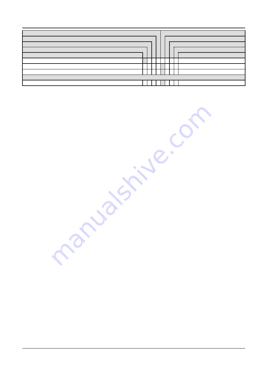
Page 32: ... fluid Replace Cleaning Drain fluid Grease Test Check Maintenance action Page no Auxiliary battery connections x Battery removal and installation x Work lights x ELECTRICAL SYSTEM Fuses and relays x 47907870 06 10 2015 23 ...
Page 33: ...nce increases with increasing speed as the weight of the towed load increases especially on hills and slopes Failure to comply could result in death or serious injury W1138A Electronic override 1 Use the multi function display screen to select the tow ing mode From the main menu scroll down and se lect Service Press the enter switch RAIL15DOZ0018AA 1 2 Scroll down and highlight the Tow Mode select...
Page 34: ...ON 3 Change the Tow Mode from Disabled to Enabled by highlighting and pressing the enter switch RAIL12DOZ0592AA 3 RAIL12DOZ0823AA 4 4 Continue to follow the screen prompts RAIL12DOZ0824AA 5 47907870 06 10 2015 25 ...
Page 35: ...DOZ0825AA 6 6 Press the enter switch to continue to the next screen NOTICE Do not tow the machine over 1 2 km h 0 7 mph RAIL12DOZ0826AA 7 7 Press the enter switch to continue to the next screen NOTICE Tow the machine the shortest possible distance RAIL12DOZ0827AA 8 47907870 06 10 2015 26 ...
Page 36: ...drostatic pump 9 Access the upper pressure relief valve by removing the floor mat 1 cab floor access panel and tilting the operator seat back The valves are located on the hydrostatic pumps beneath the cab floor RAIL12DOZ0232AA 10 10 Open pressure relief valves to bypass the hydrostatic pumps two right side valves 1 and two left side valves 2 The pumps are tandem mounted and the valves can be foun...
Page 37: ...s on each relief valve RCIL10CWL116AAL 13 Releasing the brakes NOTE This machine is equipped with a spring applied hydraulically released parking brakes Hydraulic pressure must release the brakes You MUST use a hand pump to release the brakes when the engine is not running 13 Remove the hydraulic reservoir breather Connect a vacuum pump at the hydraulic reservoir breather and hold a vacuum to keep...
Page 38: ...H12DOZ0094AA 15 15 Connect a hand pump with the capacity to reach and maintain 22 7 bar 330 psi 16 Operate the pump until the correct pressure is reached and the brakes are released 17 Check and maintain 22 7 bar 330 psi minimum in the brake line when moving the machine Damage to the brake system can result if the pressure is re duced 18 Tow the machine the shortest possible distance Do not tow th...
Page 39: ...es 2 Remove the plugs and reconnect the lines 1 to the brake solenoid RAPH12DOZ0094AA 16 3 Remove the vacuum pump and install the hydraulic reservoir breather RAIL12DOZ0372AA 17 4 Turn the engagement screws clockwise two turns on each relief valve RCIL10CWL116AAL 18 47907870 06 10 2015 30 ...
Page 40: ...nstall the floor access panel RAIL12DOZ0644AA 19 7 On the multi function display screen select Service and press the enter switch RAIL15DOZ0018AA 20 8 Scroll down and highlight the Tow Mode selection and press the enter switch RAIL15DOZ0032AA 21 47907870 06 10 2015 31 ...
Page 41: ...INTRODUCTION 9 Change the Tow Mode from Enabled to Disabled by highlighting and pressing the enter switch RAIL12DOZ0592AA 22 47907870 06 10 2015 32 ...
Page 42: ...ther parts wear rapidly F Relief valves or check valves held open by dirt G Quick failure of components that have been repaired H Cycle times are slow machine does not have enough power If your machine has any of these problems check the hydraulic oil for contamination There are two types of contam ination microscopic and visible Microscopic contamination occurs when very fine particles of foreign...
Page 43: ...esive gel The gel consistency prevents adhesive flow even on vertical surfaces 426 Black 4 8 20 7 MPa 696 3003 psi 10 sec 40 sec none Is an adhesive gel toughened with elastomers for impact and peel strength along with improved resistance to heat and humidity 454 Clear to slightly cloudy 19 28 MPa 2756 4061 psi 1 min 72 hrs none Is particularly suited for bonding porous or absorbent materials such...
Page 44: ...de retaining roller bearings or oil impregnated bushings into housings 609 Green 10 3 15 8 MPa 1494 2292 psi 25 min 6 hrs 7471 or 7469 Is designed for the bonding of cylindrical fitting parts The product cures when confined in the absence of air between close fitting metal surfaces and prevents loosening and leakage from shock and vibration Typical applications include rotor to shafts in fractiona...
Page 45: ...product possesses excellent gap cure characteristics Typical applications include restoring correct fits on worn shafts spun bearings and damaged keyways 680 Green 19 3 24 1 MPa 2799 3496 psi 20 min 1 1 hrs 7471 or 7469 Is designed for the bonding of cylindrical fitting parts particularly where low viscosity is required The product cures when confined in the absence of air between close fitting me...
Page 46: ... MPa 870 2031 psi 30 min 18 hrs 7471 or 7469 It seals close fitting joints between rigid metal faces and flanges and will flex with minor flange movements Provides resistance to low pressures immediately after assembly of flanges Typically used as a form in place gasket for pumps thermostats compressors transmission housings and axle covers 518 Red 7 5 8 5 MPa 1088 1233 psi 30 min 8 hrs 7471 or 74...
Page 47: ...embly 222 Purple 4 14 Nm 35 124 lb in 20 min 3 hrs 7471 or 7469 Is designed for the locking and sealing of threaded fasteners which require easy disassembly with standard hand tools 242 Blue 5 6 17 Nm 50 150 lb in 3 min 6 hrs 7471 or 7469 Is designed for the locking and sealing of threaded fasteners which require normal disassembly with standard hand tools 243 Blue 7 24 Nm 62 212 lb in 10 min 1 hr...
Page 48: ...ty and capillary action the product wicks between engaged threads and eliminates the need to disassemble prior to application 425 Dark blue 0 23 8 5 Nm 2 75 lb in 2 min 24 hrs 7113 Is designed as a fast curing low strength adhesive for locking metal and plastics fasteners The product is designed for pre or post application LOCTITE 425 cures quickly on plated metal and plastics fasteners fixturing ...
Page 49: ...061 024 35 314 66 1 307 950 0 033 814 1 056 814 0 879 877 0 264 172 0 219 969 cubic inch cubic foot cubic yd ounce US fluid quart US liquid quart Imperial gallon US liquid gallon Imperial VOLUME TIME litre min litre min 0 264 172 0 219 969 gallon min US liquid gallon min Imperial U S to Metric MULTIPLY BY TO OBTAIN AREA square foot acre 0 092 903 0 404 686 square meter hectare FORCE ounce force po...
Page 50: ...unce US fluid quart US liquid quart Imperial gallon US gallon Imperial 16 387 06 0 028 317 0 764 555 29 573 53 0 946 353 1 136 523 3 785 412 4 546 092 cubic centimeter cubic meter cubic meter milliliter litre litre litre litre VOLUME TIME gallon min 3 785 412 litre min 47907870 06 10 2015 41 ...
Page 51: ...This as a preview PDF file from best manuals com Download full PDF manual at best manuals com ...