- 9 -
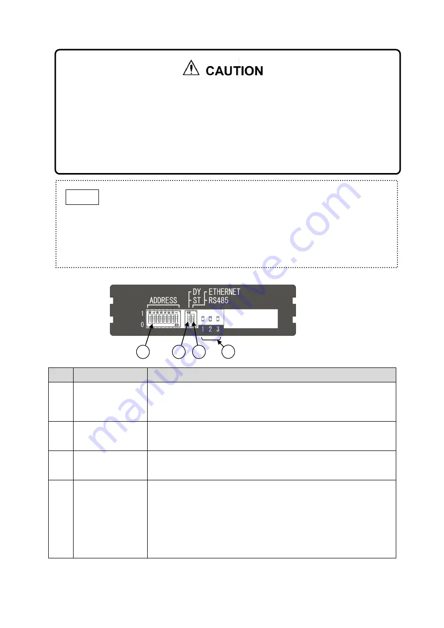
5-4. DIP Switches
Item
Component
Description/Function
1
IP Address setting
switches
Set the IP address for this product.
Settable range: 1 (0000 0001) to 254 (1111 1110).
Modbus TCP (Ethernet): Set the 4th value of IP address. *1
Modbus RTU (RS-485): Set the unit ID.
2
IP address type
switch
Switches the IP address method between DY and ST.
DY: Dynamic IP address (DHCP)
ST: Static IP address
3
Mode change
switch
Switches the mode between Ethernet and RS485.
ETHERNET: MODBUS TCP
RS485: MODBUS RTU (RS-485)
4
Status LED-1/2/3
Indicates the unit and communication statuses.
1: When flashes, LAN cable is securely connected to RJ-45 jack.
2: When flashes, Ethernet and RS-485 communications are in
progress.
3: Communication status between the base and main unit.
- When flashes, communication is normal (sending and receiving)
- When steady, no response from the main unit.
- When not lit, no request from the base unit.
*1: When the IP address is
“0 (0000 0000)”, the IP address can be changed by using a web browser.
1
2
4
3
Set the base unit power switch to the OFF position before using the DIP switches to avoid
incorrect operation or device failure.
Do not use IP address “255 (1111 1111)” because LAN Communication will be disabled if
that IP address is used.
Set the DIP switches in accordance with your selected communication method. Refer to
the PS-7-M communication specifications guide for details.
Ensure that each switch is clearly set to the 1/0, DY/ST, and Ethernet/RS485 positions.
Unclear setting may result in incorrect operation/communication.
The IP address settable range is 1 (0000 0001) to 254 (1111 1110).
When the IP address is
“0 (0000 0000)”, it will be superseded by the IP
address set by a web browser.
IP address can be set to any value within the settable range, but if the same
address is used by more than one detector, the relevant detectors cannot
communicate.
The IP address settable range is 1 to 254.
NOTE


