background image

optical

CON powerMONITOR 


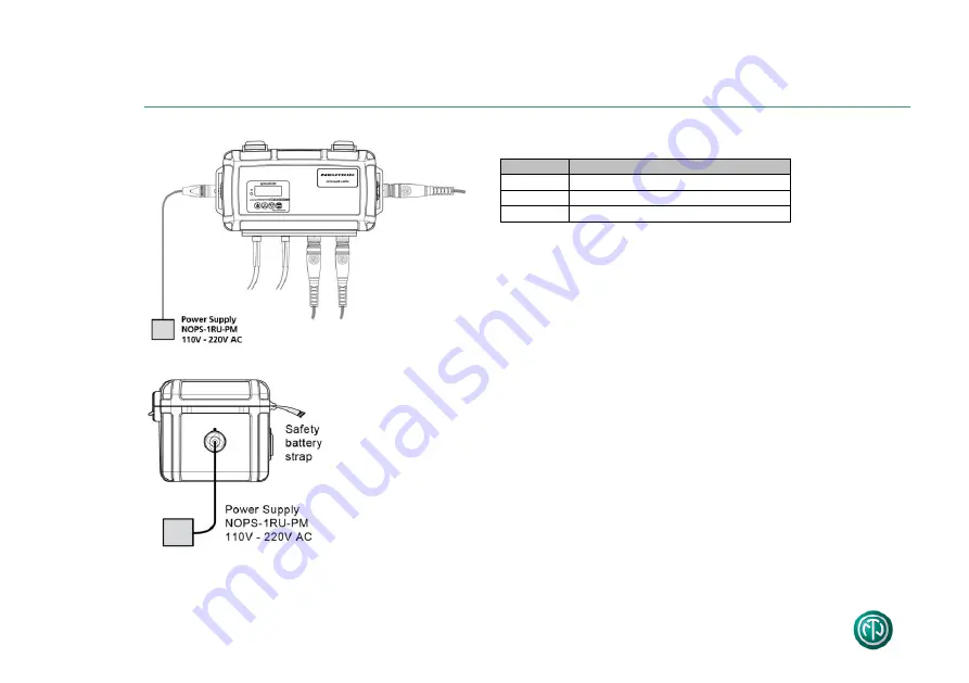
... Keys And Connectors 


No 

Function 

10 

Fiber input - opticalCON 

11 

Fiber output - opticalCON or LC 

12 

Power 5V DC 


To change the batteries, occur following steps: 
- remove safety cable tie 
- open cover  
- remove battery holder screws 
- replace batteries  
- close cover and secure with safety cable ties 


Before use the powerMONITOR remove safety battery 
strap. 

11 opticalCON NKO2*/LC 

Summary of Contents for opticalCON powerMONITOR

Page 1: ...version 1 4 opticalCON I powerMONITOR User Manual...

Page 2: ...5 C Do not heat the battery above 60 C Do not dispose of the battery by burning Do not solder directly to the battery Do not disassemble the battery Do not insert the battery in reverse polarity The L...

Page 3: ...and Connectors 5 4 Software Main Menu 7 5 Channel Reset Threshold Selection 8 5 1 Change Channel Designation 9 6 Mode Wavelength Selection Single mode 10 6 1 Mode Wavelength Selection Multimode 11 7 B...

Page 4: ...ack painted Connectivity opticalCON LC Return loss 45 dB Insert loss 0 5 dB Factory calibration 5 dBm 0 1 12 dBm 0 3 24 dBm 0 5 Area of operation SM 3 dBm to 30 dBm Wavelengths single mode 1310 1550 n...

Page 5: ...er ON OFF button 2 UP botton 3 Down button 4 INFO SET button 5 Relative attenuation 6 Absolute attenuation 7 Charging character 8 Chosen channel 9 Threshold level 10 Fiber input opticalCON 11 Fiber ou...

Page 6: ...tput opticalCON or LC 12 Power supply 5V DC To change the batteries occur following steps remove safety cable tie open cover remove battery holder screws replace batteries close cover and secure with...

Page 7: ...NITOR 7 4 Software Main Menu Attention WDM modus at the Wavelength section is only on single mode available If the powerMONITOR turns on an internal test starts and checks the proper functionality of...

Page 8: ...using or 2 To enter Ch1 menu push twice This will reset the relative attenuation 3 Select the current threshold level dB by pushing or and finally to save 4 The secondary line indicates the chosen thr...

Page 9: ...ange the channel designation press or till display indicates Ch1 info menu and confirm with 4 Change the displayed symbol by using or and select character with 5 Repeat step 3 and 4 for additional cha...

Page 10: ...elect the Wavelength Menu using or 2 Push twice to modify the settings 3 Hit or to switch between the wavelengths and WDM section SM 1310 1550 nm WDM MM 850 1300 nm 4 Push to save the settings Now the...

Page 11: ...ng or 2 Push twice to modify the settings 3 Hit or to switch between following wavelengths and type of light source Symbol Description MM850 LED 850 nm multimode LED light source MM850 VCSEL 850 nm mu...

Page 12: ...sing or 2 Press 3 Press or to switch between the two charging modes 4 To set a mode press Mode Function Dis Charge Discharges battery before recharging gently Charge anyway Starts battery charging imm...

Page 13: ...attery mode 2 Hit 3 To switch between the battery mode press or and confirm with Mode Function ACCU Auto Depending on the battery status the power MONITOR starts to discharge charge automati cally gen...

Page 14: ...e example on top the powerMONITOR exhibits 6 dBm which means 1 dB attenuation in reference to the output power of 5 dBm The following matrix exhibits the attenuation accuracy tolerances of absolute an...

Page 15: ...m 2kHz mode The difference of the output power dB is the total atten uation of the system cable devices The difference between the recent power budget and the system attenuation shows the correspondin...

Page 16: ...LTD Workshop 14 16 Floor Wah Wai Centre Nr 38 40 Au Pui Wan Street Shatin T 852 2687 6055 neutrik neutrik com hk Great Britain Neutrik UK Ltd Westridge Business Park Cothey Way Ryde Isle of Wight PO33...

Reviews: