

®
ASSEMBLY INSTRUCTION - opticalCON DRAGONFLY NKO2SMW-XP-*
I
Plug side / Device
A
B
D
3x
*
C
2
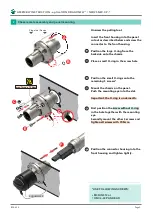
Chassis male assembly and panel mounting
Page 2
BDA 632
* USE FOLLOWING SCREWS:
M3 DIN 912 or
UNC 4-40 PAN HEAD
Unscrew the pulling tool.
Insert the front housing into the panel
cutout as described below and screw the
connector to the front housing.
Position the large O-ring from the
backside onto the chassis.
Place a small O-ring in the screw hole
Position the small O-rings onto the
remaining 3 screws*.
Mount the chassis on the panel.
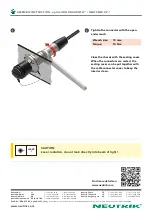
Push the mounting eye into the slot.
Important: the O-ring is underneath.
First position the screw without O-ring
in the hole together with the mounting
eye.
Secondly mount the other 3 screws and
tighten all screws with 70 Ncm.
Position the connector housing into the
front housing and tighten lightly.
A
B
C
D
E
F
F
SCNO2MW-XP
max. Torque 70 Ncm
E


