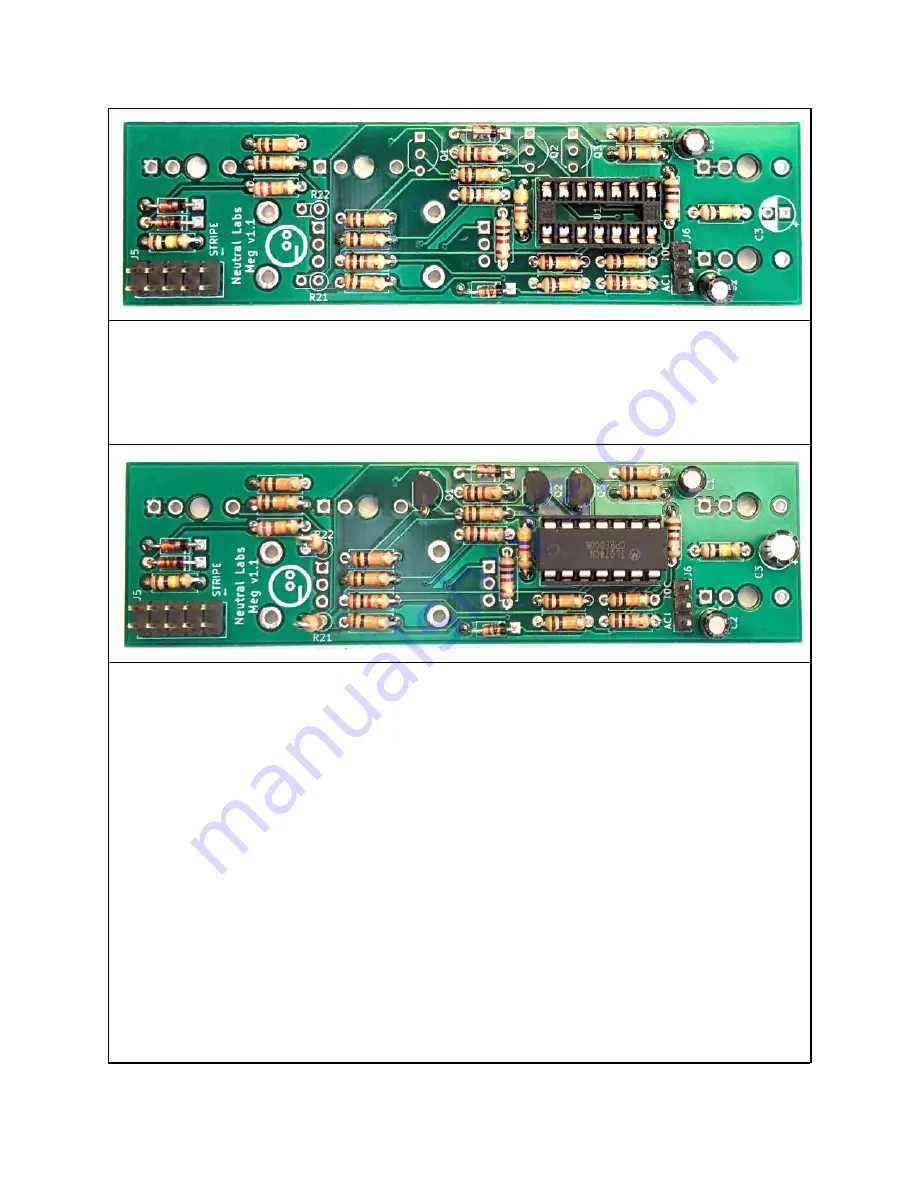
Add the 2x5 pin power header (J5) and the 3-pin header (J6). As with
the IC socket, it’s best to solder a single pin first. You may want
to hold the headers in place with a piece of sticky tape while
soldering. Another trick is to plug the Eurorack power cable into the
header before and hold it this way.
Now on to C3 (pay attention to the polarity) as well as the 3
transistors
Q1,
Q2
and
Q3.
Again,
polarity
matters
for
the
transistors. Insert them facing them as the outline on the PCB
indicates. Make sure that the transistors labeled J109 go into Q1 and
Q2 and the 2N3904 goes into Q3. They’re very different beasts and not
interchangeable!
Remember the 2 remaining resistors (R21, R22)? Now’s their time to
shine: Put them into their places as shown on the picture. They’ll
stand up instead of lying down, which is totally not because of space
limitations on the PCB, but rather in order to better absorb cosmic
energy at a specific, um, wavelength. Trust me!
Plug the IC into its socket (U1). It has a little notch on it which
should match the little notch on the socket (and the notch in the
white outline on the PCB). Bend its legs slightly inward if you have
trouble fitting it in. Put the little green jumper on the 3-pin
header (in any position, see the manual). Now flip the PCB over.


