background image

KH 805  |  

I

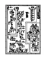
System block diagram/System-Blockdiagramm/

Synoptique système/Diagrama de bloques del sistema

Note: “Daisy Chain“ bypasses all acoustical control settings, so the first subwoofer in the chain becomes a “master“ with subsequent subwoofers being “dumb slaves“.
Note: As the KH 810 does not have volume control on the SUM OUT, when the KH 750 is used for a “Daisy Chain“ the volume control must be done in the source.

Left

Daisy Chain

LFE (Wide)

Right

LFE (120 Hz)

Right

Channel

Input Mode

Left

Right

Right / LFE /
Daisy Chain

Daisy Chain

Low Cut Parametric

Phase

Output

Level

0 ... -12

+4   20    1

180

Fine   Coarse

Power/
Protect

Remote Control

Bass Management

Bypass

0

45
90

135

-12  120   8

Gain

Power

on Mute

Limiter /
Soft Clip

SMPS

80

80

80

120

Σ

Σ

Σ

Pin assignment of the XLR socket/Buchsenbelegung XLR/

Brochage de la prise XLR/Asignación de la hembra XLR

1

Audio ground/Audio-Erdung/Masse audio/Toma de tierra de audio

2

///Señal +

3

Signal −/Signal −/Signal −/Señal −

Pin assignment of the REMOTE CONTROL socket/

Anschlussbelegung der Buchse REMOTE CONTROL/

Brochage de la prise REMOTE CONTROL/Asignatión de 

conexiones de la hembra REMOTE CONTROL

Jack plug/Klinkenstecker/

fiche jack/conector jack

Function/Funktion/Fonction/Función

Tip

Bass Management *

Sleeve

Ground/Erdung/Masse/Toma de tierra

Short the tip and sleeve together to bypass the bass management

NOTE: There is a 9 V DC supply on the tip connection of this socket so that an LED can be lit 
up to show when the bass management is on. Many guitar amplifier foot switches have this 
function.
HINWEIS: An der Buchsenspitze liegt eine Spannung von 9 V DC an, damit eine LED den Status 
des Bass Managements anzeigen kann. Viele Fußschalter für Gitarrenverstärker verfügen über 
diese Funktion.
NOTE : Une tension de 9 V CC est présente à la pointe de la prise pour qu‘une LED puisse affi-
cher le statut du bass management. Beaucoup de pédales pour ampli de guitare disposent de 
cette fonction.
NOTA: A la punta de la hembra llega una tensión de 9 V DC para que un LED pueda indicar el 
estado de la función Bass Management. Muchos interruptores de pedal para amplificadores de 
guitarra incorporan esta función.

Summary of Contents for KH 805

Page 1: ...r Str 112 10117 berlin germany tel 49 0 30 417724 0 fax 50 headoffice neumann com www neumann com KH 805 Active Subwoofer with 2 1 0 1 Bass Management Operating Manual Bedienungsanleitung Manual Utili...

Page 2: ...g the subwoofer on off 15 Calibrating the subwoofer 15 Compensating for larger time of flight TOF differences 18 Using the bass management 18 Setting the replay level of the subwoofer 19 Activating gr...

Page 3: ...s When a cart is used use caution when moving the cart apparatus combination to avoid injury from tip over 13 Unplug this apparatus during lightning storms or when unused for long periods of time 14 R...

Page 4: ...und pressure levels exceeding 85 dB A SPL This is the sound pres sure corresponding to the maximum permissible level which is by law in some countries allowed to affect your hearing for the duration o...

Page 5: ...motely controlled State of the art circuitry design and the specially developped long excursion bass driver have been used to ensure the most accurate sound reproduction possible Neumann products are...

Page 6: ...KH 805 5 Product overview 1 2 3 3 1 Neumann logo 2 Metal grille 3 Bass reflex ports...

Page 7: ...ALIZER Q PARAMETRIC EQUALIZER FREQUENCY A PARAMETRIC EQUALIZER switch B INPUT GROUND LIFT switch C Sockets INPUT RIGHT LFE DAISY CHAIN INPUT LEFT D Sockets OUTPUT DAISY CHAIN OUTPUT RIGHT OUTPUT LEFT...

Page 8: ...in an air gap of at least 2 5 cm around the subwoofer s backplate to ensure a free air flow through the ventilation openings For information on installation please refer to the supplied Getting Starte...

Page 9: ...using the Neumann REK 3 remote electronics kit and an SC cable available in different lengths see Accessories on page 24 Using one or several subwoofers X X Use one subwoofer several subwoofers if yo...

Page 10: ...ing Max spacing of the subwoofer cabinets RIGHT approx 2 m 6 6 LFE 120 Hz approx 1 4 m 4 6 LFE WIDE approx 1 4 m 4 6 DAISY CHAIN depends on setting of first subwoofer If you observe the stated spacing...

Page 11: ...ntation of your loudspeakers please refer to the operating manuals of the loudspeakers If your subwoofers cannot be placed at the same distance from the listening position as the loudspeakers time of...

Page 12: ...e subwoofer to the input sockets of the loudspeakers as shown in the following diagrams Stereo two loudspeakers Full range stereo bass managed two loudspeakers and one subwoofer L R L Sub Right Channe...

Page 13: ...b Right Additional subwoofers can be added to the L R Sub and or LFE Sub using the setting Daisy Chain Full range large multichannel system with bass management in the source equipment Full range larg...

Page 14: ...After calibrating the main loudspeakers the subwoofers should be acoustically calibrated so that they smoothly extend the bass response of their respective main loudspeaker down in frequency from 80...

Page 15: ...ins plug of the mains cable to a suitable wall socket To disconnect the KH 805 from the mains power supply X X Set the switch MAINS POWER 5 to OFF X X Pull the mains plug out of the wall socket Mounti...

Page 16: ...rst time and whenever you change the physical conditions in your studio carry out the following steps X X Adjust the frequency response and the level of the loudspeakers before calibrating the sub woo...

Page 17: ...asurement system The settings of the switch SUBWOOFER GAIN OUTPUT LEVEL H and the potentiometer SUBWOOFER GAIN INPUT GAIN J recommended in the following table are valid for the following settings of y...

Page 18: ...M to the opposite position The phase shift between loudspeaker and subwoofer is now 0 Check your subwoofer s sound pressure level again and if necessary readjust it so that it corresponds to the sound...

Page 19: ...audio signals below 80 Hz to the subwoofer The LED BASS MANAGEMENT G lights up green If you deactivate the bass management the audio signal of the audio outputs OUTPUT LEFT and RIGHT D is only reprodu...

Page 20: ...m to On This is typically achieved by setting the loudspeaker size to Small X X In the source switch the subwoofer output to On X X In the source choose a crossover frequency of 80 Hz X X In the sourc...

Page 21: ...und from the input signals activating ground lift To activate ground lift X X Reconnect the signal cables and set the switch INPUT GROUND LIFT B to LIFTED This internally disconnects pin 1 of the XLR...

Page 22: ...t lay signal cables parallel to mains cables use balanced cables use the ground lift switch see page 19 or send higher signal levels from your source and reduce the level on your subwoofer and your mo...

Page 23: ...ain 4 to 12 dB frequency 20 Hz to 120 Hz Q factor 1 to 8 Time of flight adjustment delay 0 to 315 adjustable in steps of 45 Output level control for a 0 dBu input signal at 1 m in free field condition...

Page 24: ...nd storage packed in original packaging 25 C to 70 C 13 F to 158 F Relative humidity Operation and storage unpacked max 75 non condensing Transport and storage packed in original packaging max 90 non...

Page 25: ...lectronics kit SC 2 Subwoofer cable 2 m SC 5 Subwoofer cable 5 m SC 10 Subwoofer cable 10 m SC 15 Subwoofer cable 15 m SC 20 Subwoofer cable 20 m SC 25 Subwoofer cable 25 m SC 30 Subwoofer cable 30 m...

Page 26: ...03 Incl AM1 and UL Std No 60065 2007 Trademarks Neumann is a registered trademark of Georg Neumann GmbH The following are trademarks of Georg Neumann GmbH Plane Wave Bass Array and PWBA Other company...

Page 27: ...s generally achieved using a sound level meter set to C weighted and Slow Play a broadband pink noise test signal set to 18 dBFS Europe or 20 dBFS USA on the console meters and measure the sound press...

Page 28: ...ge 9 and due to different distances of the subwoofers and loudspeakers from the listening position Examples of how to calculate sound pressure levels as a function of the input signal levels and input...

Page 29: ...ubwoofer thereby giving greater flexibility when placing the subwoofer in the room In addition by choosing 80 Hz there is a compatibility with the replay conditions commonly found in consumer products...

Page 30: ...the REMOTE CONTROL socket Anschlussbelegung der Buchse REMOTE CONTROL Brochage de la prise REMOTE CONTROL Asignati n de conexiones de la hembra REMOTE CONTROL Jack plug Klinkenstecker fiche jack cone...

Page 31: ...e de notre site Web ES Las siguientes mediciones ac sticas se han realizado bajo condiciones de baja reflexi n a una distancia de 1 m Encontrar versiones a color de estos diagramas en las p ginas corr...

Page 32: ...bajos Low Cut Parametric Equalizer Parametrischer Equalizer Action de l galiseur param trique Control del ecualizador param trico dB 0 5 10 15 0 005 0 02 0 1 0 5 1 kHz dB 0 5 10 15 0 005 0 02 0 1 0 5...

Page 33: ...07 15 560090 A01...

Reviews: