


13
• Connecting the Power
Connect the power of
12 VDC
or
24 VAC
for the network camera. Connect the positive (+) pole to
the ‘+’ position and the negative (-) pole to the ‘-’ position for the DC power.
Be careful not to reverse the polarity when connecting the power cable.
A router featuring PoE (Power over Ethernet) can also be used to supply power to the
camera.
The heater will operate properly only by the power source of AC 24V.
For the power specifications, refer to the Appendix, Product Specification.
If PoE and 12 VDC are both applied, the camera will be supplied with power from PoE.
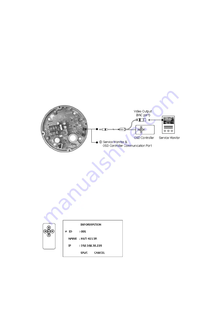
• Connecting Service Monitor Port
Service monitor output port (J7) is located on the board of the dome camera, and is used for an
easy OSD setup.
▶
ID & IP assignment
To make changes in the OSD menu, please use the OSD controller provided optionally with your
camera purchase. You can set Camera Title and IP Address.
1.
Connect the OSD Controller to the Service Monitor port of the network camera.
2.
Connect Service Monitor and the Video Output port of the OSD Controller.
3.
Press the SET button to access main Menu.
4.
Change Camera ID, and IP Address. You can change the Name or Title and IP address of the
camera. Using the
↑↓←→
buttons on the controller, you can change the parameters.
5.
Select SAVE or CANCEL to exit the Main Menu.
Video Output is also used for an easy zoom and focus control when installing lens. Video Output
is restricted to 704x480(576) resolution.
Note: You can get the Optional OSD Controller from your installer.
▶
Zoom & Focus Control


