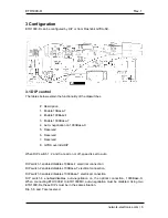
Network Electronics Flashlink ETH1000-D User Manual Download Page 5

ETH1000-D  

Rev. 


2 Specifications 

2.1 Optical Characteristics 

Optical input 

Transmission circuit fibre: 

9/125um Single Mode 

Sensitivity 

Better than –25dBm 

Optical wavelength 

1200nm – 1610nm 

Detector damage threshold 

> +1dBm 

Max input power 

0dBm 

Connector SC/UPC 

 
Optical Output 

Transmission circuit fibre 

9/125um Single Mode 

Light source 

DFB DWDM Laser 

Optical wavelength 

1530.33nm - 1561.41nm, 40 C-band DWDM channels acc. to 
ITU-T G.694.1 

Channel spacing 

100GHz 

Power output   

0dBm (+5dBm for high power version) 

Extinction ratio 

>  10:1 

2.2 Ethernet 

10BaseT/100BaseTx/1000BaseT on RJ-45 connectors. Compliant with IEEE 802.3, IEEE 
802.3u, IEEE 802.3ab and IEEE 802.3z. Auto speed sensing and MDI/MDI-X. 

2.3 General 

Power  

+5V DC/2.5W and +15V DC / 0.5W 

Control 

Control system for access to setup and module status with 
BITE (Built-In Test Equipment) 


network-electronics.com 

Summary of Contents for Flashlink ETH1000-D

Page 1: ...network electronics com Gigabit Ethernet Media Converter with DWDM laser Rev 1 Flashlink User Manual ETH1000 D...

Page 2: ...support network electronics com www network electronics com Support Phone 47 90 60 99 99 Revision history Current revision of this document is the uppermost in the table below Rev Repl Date Sign Chang...

Page 3: ...unting the connector module 8 4 2 Terminal format support 9 5 Module status 10 5 1 Front panel Status monitoring 10 5 2 GPI Alarm Module status outputs 11 6 Laser safety precautions 12 General environ...

Page 4: ...nd one fibre transceiver port receiver fibre connector and transmit fibre connector The speed on the electrical connector is dependent of the DIP switch setting or GYDA control Speed will upon link co...

Page 5: ...ource DFB DWDM Laser Optical wavelength 1530 33nm 1561 41nm 40 C band DWDM channels acc to ITU T G 694 1 Channel spacing 100GHz Power output 0dBm 5dBm for high power version Extinction ratio 10 1 2 2...

Page 6: ...P When DIP switch 1 2 and 3 are all on or off speed is set to auto DIP switch 1 enables disables 10Base T electrical connection DIP switch 2 enables disables 100Base T electrical connection DIP switch...

Page 7: ...er identifier lsr status D wavelength nm power dBm on off ok fail tempfail stab block command operation operation on off 3 2 1 2 PIN identifier pin status cd ncd 3 2 1 3 Voltage identifier pwr status...

Page 8: ...rack The module is shown in the figure below OPT TX GPI OPT RX 10 100 1000Base T 4 1 Mounting the connector module The details of how the connector module is mounted is found in the user manual for t...

Page 9: ...elow shows the input and output signals on the back plane Terminal format support Terminal Function Supported Format Mode OPT RX Optical input 1000Base X Input OPT TX Optical output 1000Base X Output...

Page 10: ...ront panel Status monitoring The status of the module can be easily monitored visually by the LED s at the front of the module The LED s are visible through the front panel as shown in the figure belo...

Page 11: ...riggered The GPI connector is shown in figure below GPI pinning Signal Name Pin Mode Status General error status for the module Pin 1 Open Collector LOS Loss of optical signal Pin 2 Open Collector LIN...

Page 12: ...g fibre pigtails ends Never look directly into the pigtail of the laser fibre Never use microscopes magnifying glasses or eye loupes to look into a fibre end Use laser safety goggles blocking light at...

Page 13: ...cification under the following environmental conditions Operating room temperature range 0 C to 40 C Operating relative humidity range 90 non condensing 2 The equipment will operate without damage und...

Page 14: ...nd conditions for the product s covered by this manual follow the General Sales Conditions by Network Electronics AS These conditions are available on the company web site of Network Electronics AS ww...

Page 15: ...oxic or hazardous substance contained in at least one of the homogeneous materials used for this part is above the limit requirement in SJ T11363 2006 This is indicated by the product marking A 2 Recy...

Page 16: ...04 108 EEC HARMONISED STANDARDS applied in order to verify compliance with Directive s EN 55103 1 1996 EN 55103 2 1996 TEST REPORTS ISSUED BY Notified Competent Body Report no Nemko E08462 00 TECHNICA...

Reviews: