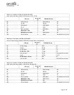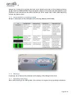
Page 89/ 191
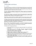
11.2 Location and mounting
The protective capsule must be sited in the vicinity of the bridge on the external deck area of the
vessel to maximize the probability of its survival and recovery following an incident.
Criteria to be considered when assessing the optimum position shall include but not be limited to
the following:
•
Separation from fuel or other potential fire sources.
•
Separation from probable sources of mechanical damage.
•
Operational environment for continued serviceability.
•
Accessibility for copying of recorded data and for routine maintenance.
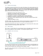
The TRON 40 shall be sited in the vicinity of the bridge on the external deck area of the vessel
to maximize the probability of its survival and recovery following an incident.
During replacement and new installation of TRON 40VDR it is important to pay attention to the
location of the TRON40 Float Free Capsule. Strong RF signals from radars or other transmitting
antennas can cause communication errors which in turn can result in malfunctioning of the TRON
40VDR.
It is recommended to test the position of the Jotron device with a flying cable and an ICMP test
first, before installing it (see paragraph ‘Connection test with flying cable’).
Take following aspects into account for choosing the mounting location of the TRON 40VDR.
-
It is not recommended to locate the TRON 40VDR on the compass deck because of high
risk of exposure to strong RF signals.
-
Find a new mounting location as far away as possible from any radar interference and/or
other antennas conform Jotron specifications (see Jotron installation manual). Make sure
the TRON 40VDR is not directly in line of sight of any radar, and at least 3 meters away
from any antenna.
-
Stronger antenna signals (than the TRON 40VDR is approved for) can affect the VDR
storage performance.
The TRON 40VDR is approved for 100 V/m in the VHF frequency range 156 - 165 MHz.
In other areas of the frequency range 150 kHz - 2 GHz the requirement is 10 V/m. A
standard VHF antenna will have 10 V/m at distance of 3 meters in the antenna lobe.
Therefore, the absolute minimum distance to a VHF antenna, at the same height needs to
be no less than 3 meters. It is strongly recommended to have a much larger distance to
other transmitting antennas.
-
RF signals from transmitting antennas are likely to be weaker at low levels. Therefore,
reduction of interference may be achieved by installing the TRON 40VDR lower than all
transmitting antennas.
-
It is recommended to find a location with “natural” shade from the radar systems. This
would typically be on a wing opposite to the radar mast.
Summary of Contents for NW6000
Page 1: ......
Page 91: ...Page 91 191...
Page 92: ...Page 92 191...
Page 120: ...Page 120 191 Figure 17 4 2 Connection figure Digital Module 16 channels...
Page 121: ...Page 121 191 Figure 17 4 3 Connection figure Digital Module 24 channels...
Page 125: ...Page 125 191 Figure 18 4 2 Connection figure Analogue Module 8 channels...
Page 126: ...Page 126 191 Figure 18 4 3 Connection figure Analogue Module 12 channels...
Page 184: ...Page 184 191 Figure 5 8 1 Sample dataset playback...


