Page 169/ 191
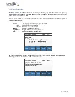
2.7 Alert conditions indicated on BCU
Any recording errors, being it data integrity, loss of sensor information or other circumstance as
represented in the VDR Performance Standard will lead to an ALERT condition which stays active
and displayed on the BCU. In case the ALERT is resolved, the text line will disappear.
Following indications can appear on the BCU.
(Between brackets time that ALERT is active) followed by ALERT indication:
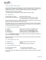
2.7.1 Power Failure
A)
‘Power failure (230 V gone)’
Mains power (230 Vac) is lost.
B)
‘Power failure: recording stopped’ When main power was lost for more than 2 hours
By regulation/design the recording will be stopped.
Any power source which has been available at system start-up and which is disconnected (or lost
its power) thereafter will generate a Power Failure ALERT.
If the primary power source is lost, the battery-backup mechanism will secure continued operation
of the VDR. In battery-backup mode, the VDR will continue to operate for 2 hours, after which time
the VDR will switch off until normal power is restored.
2.7.2 Recording Channels NMEA
A)
‘No data: … ‘
NMEA data is not received on the NMEA channel
B)
‘No time on: ... ‘
No time received on configured NMEA channel
C)
‘No position on: ...’
No position received on configured NMEA channel
D)
‘No heading on: … ‘
No heading received on configured NMEA channel
If any of the
designated channels
loses its signal an ALERT will be presented, including the
source (channel name) of that signal.
Designated Channels are those which have been set to active during commissioning and therefore
have to be recorded.
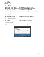
2.7.3 Recording channels audio
A)
‘No audio from: … ‘
No audio from specific microphone or VHF
Interface.
B)
‘Audio test failed on …’
Audio test failed on specific microphone.
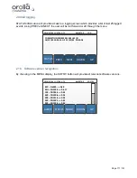
2.7.4 Recording channels video data
A)
‘Video connection problem’
No connection to the video device.
B)
‘No image from: … ‘
No image received from specific video port.
In the event of absence or malfunction of the video adaptor or the radar video signal, an ALERT
is generated.
Summary of Contents for NW6000
Page 1: ......
Page 91: ...Page 91 191...
Page 92: ...Page 92 191...
Page 120: ...Page 120 191 Figure 17 4 2 Connection figure Digital Module 16 channels...
Page 121: ...Page 121 191 Figure 17 4 3 Connection figure Digital Module 24 channels...
Page 125: ...Page 125 191 Figure 18 4 2 Connection figure Analogue Module 8 channels...
Page 126: ...Page 126 191 Figure 18 4 3 Connection figure Analogue Module 12 channels...
Page 184: ...Page 184 191 Figure 5 8 1 Sample dataset playback...


