background image

Dedicated Micros ©2011

38

CamV

u 500 VR Dome

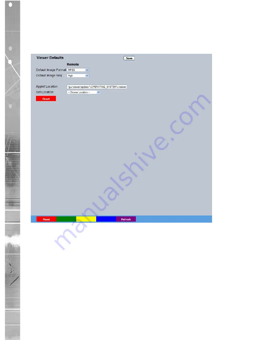
Viewer Defaults 

The units Viewer function allows remote users to simulate local operation over a network. This menu 

allows configuration of settings for the Viewer function, refer to ‘Operating The Viewer’ for more information 

regarding the Viewer.

Default Image Format 

Camera images can be displayed in either JPEG or MPEG format on 

the LAN (local area network) and the WAN (wide area network).

Default Image Req 

The default size for images displayed full screen in the Viewer menus 

on the LAN and the WAN can de set at High, Medium, Low or None. 

Applet Location 

The location of the unit’s Viewer menu applet is displayed. The default 

location will always be the applet installed on the unit. If accessing 

multiple units via a remote connection, all can be assigned the same 

Viewer applet. This will lessen the load time required when accessing 

different DVRs/Servers. 

For example, if a local unit and a remote DVR are to be accessed, it 

is possible to set the Applet location for both DVRs as the local unit. 

If viewing the unit remotely, Dedicated Micros provide a remote applet 

located on the Dedicated Micros website (www.dedicatedmicros.

com/software_release/windows/viewer-applet.jar). Due to possible 

bandwith restrictions on the network the DVR is located, using this 

remote applet may improve data transfer speeds.

Summary of Contents for CamVu500

Page 1: ...CamVu500 Vandal Dome Installation and Configuration Manual DM CMVUVRD500 DM CMVUVRD500 N ...

Page 2: ...rm 63 Network 79 Features Text 96 Diagnostics 101 Event Search 103 Unit Operation 105 Appendix A 119 Appendix B 126 Appendix C 127 Specification 128 Notes 130 Index 131 Whilst every attempt is made to ensure these manuals are accurate and current Dedicated Micros reserve the right to alter or modify the specification of the machine described herein without prejudice ...

Page 3: ... Tripwire and Counting Tripwire all locally hosted on the camera VANDAL RESISTANT Designed for installations where cameras could be susceptible to deliberate or accidental damage or where they are exposed to harsh environmental conditions such as dust the CamVu500 dome is built from impact resistant aluminium constructed to an IP66 rating 11381 CLOSED IPTV Dedicated Micros award winning Closed IPT...

Page 4: ... record rate compression MPEG 4 JPEG H 264 settings Web server for remote configuration of camera features Local analogue test monitor output for use when positioning and adjusting the camera s field of view and focus Uses the latest Chipwrights ViSP to minimise power consumption and heat build up Benefits The camera supports recording to local SD card or network attached storage using ATA over Et...

Page 5: ...t up to 16A EN 50130 4 Immunity requirements for components of fire intruder and social alarm systems EN 60950 Safety of IT and similar equipment Further details about these applicable standards can be obtained from Dedicated Micros Ltd 1200 Daresbury Park Daresbury Cheshire WA4 4HS 1 01002 RF Interference warning This is a class B product In a domestic environment this product may cause radio fre...

Page 6: ...en the equipment is operated in a commercial environment This equipment generates uses and can radiate radio frequency energy and if not installed and used in accordance with the instruction manual may cause harmful interference to radio communications Operation of this equipment in a residential area is likely to cause harmful interference in which case the user will be required to correct the in...

Page 7: ...ble use the ethernet connection otherwise a suitable 12Vdc 0 5A PSU is required Alternatively a 12Vdc PSU VS PSU15W EXT can be purchased from Dedicated Micros INSTALLING YOUR CAMERA Network and power cables enter the camera body inside a plastic or metal conduit either from the side or rear of the camera refer to Appendix B for a scale pattern 1 Loosen the four torx screws on the front of the came...

Page 8: ... of the camera you may wish to fit a conduit in position temporarily at the side of the camera to align the camera before marking the screw holes If the video and power cables enter from the rear of the camera mark and drill a hole for the conduit and leads The size of hole required depends on the size of the conduit 6 Attach a metal or plastic conduit with a suitable M20 screw thread to the side ...

Page 9: ... if not using PoE connect the power cable to the power terminals The camera operates from a 12V DC power supply Connections and polarity are indicated next to the terminals The power supply must be a UL Listed Class 2 isolated type Note A CAT5 cable must be used 9 Fit the camera assembly back into its body and tighten the two captive screws ...

Page 10: ...s described in the Camera Settings section 11 Visually align the screws on the dome front cover with the screw holes on the camera body to assist in replacing the dome cover 12 The CamVu 720 supports two normally open closed alarm inputs via multiway connector arrowed in the image below Alarm Connection Table Label Key Connection 0 A Alarm 1 GND B Alarm 1 1 C Alarm 2 GND D Alarm 2 ...

Page 11: ...rectional audio Connect the audio equipment using a 3 5mm 90 jack plug to the phono socket shown in the image below Audio Connection Information 3 5mm phono socket 8KHz 16KHz 22KHz sampling 75Ω input impedance 1V pk pk amplification req on output Sleeve ground Tip audio out Ring audio in 15 Replace the dome front cover and tighten the torx screws taking care not to trap the retaining cord in the e...

Page 12: ...ard is turned ON Power over Ethernet The camera can be powered from any suitable PoE injector conforming to IEEE 802 3 2008 End span and bridging injectors supported POE Injector The Dedicated Micros POE Injector is designed to enable the use of POE Power over Ethernet before a POE capable switch has been installed It is installed alongside a suitable 48Vdc 15W PSU DM PSU 48V can be purchased sepa...

Page 13: ...ould cause irreparable damage Note Layer 3 Enhanced Switch shown normal Ethernet switch or DVR NVR connection also compatible CamVu2000 camera shown RJ45 socket on dome is compatible POE Injector Power Supply specification Adaptor socket 5 5mm diameter with a 2 1mm central circular pin 48V goes to the centre pin of the power connector 0V to the outside barrel CAMERA SETTINGS HYPERD VERSIONS ONLY ...

Page 14: ... network switch or router it is connected to Most routers will have the facility to enable DHCP and DNS if it is not available contact your network administrator The default DNS address for each unit is factory set as the serial number This address can be found on the serial label on the unit or via the packaging the unit came in If DHCP and DNS are not available the IP address can be found by con...

Page 15: ...referably on a PC on the same subnet as the unit 6 12 2 Type the IP address or DNS name if there is no fixed IP address of the unit into the address bar 3 If prompted enter a username and password The default settings are username dm and password web 4 The Main Menu page will be displayed 6 13 The configuration menus are accessible via the link on the left hand side of the page ...

Page 16: ...e page allows the unit time and date settings to be adjusted including setting the timezone The Audio page shows the settings available for each of the audio channels and allows configuration of audio quality The Features page allows control of the different features that are available within the software including Email reporting and control of the display resolution The Maintain page allows the ...

Page 17: ...ys the date time of the earliest recording held on the unit System Name This field can be edited to allocate a name to the unit which can be typed directly into a browser to access the configuration pages on a DNS enabled network This is displayed when the unit is accessed via NetVu ObserVer and is sent when transmitting information to a Remote Video Response Centres RVRC MAC Address This is the M...

Page 18: ...s Shows the number of camera channels on the unit Global PPS Details the unit Global PPS Pictures Per Second recording rate Video Storage Gbytes Highlights the available video storage capacity in Gigabytes Software Red Links to the System Software details page ...

Page 19: ... VR Dome Software This page details the installed software and may be needed if calling Technical Support System Red Links back to the System Settings page About Blue Opens the System About page Refresh Purple Refreshes the current page ...

Page 20: ...en operating and the time since its last reset Time since last reset Details the time since the unit was last reset Total running time Details the total time the unit has been operational Reset code The last reset code used is displayed Restart reason The reason for the last restart is displayed i e Controlled User Reset Refresh Purple Refreshes the current page ...

Page 21: ...tes the contact is closed dark green indicates it is open Alarm Zones Details the status of the four alarm zones on the unit Light Green indicates the zone is active dark green indicates it is passive Relay Outputs Details the status of the relay output on the unit Light Green indicates the relay is closed dark green indicates it is open Alarms Blue Opens the Alarm Inputs page Refresh Purple Refre...

Page 22: ...ndix A General Information Record Details Opens the Record Details page refer to Appendix A Record Details Camconfig Details Opens the Camconfig Details page refer to Appendix A Camconfig Details Capabilities Opens the Capabilities Details page refer to Appendix A Capabilities Details UI Information Opens the UI Information page refer to Appendix A UI Information Profile Record Tables Opens the Pr...

Page 23: ... 2011 23 CamVu 500 VR Dome Logs The log files stored in the camera can be accessed from this page Selected logs are displayed on the page below About Blue Opens the About page Refresh Purple Refreshes the current page ...

Page 24: ...e Enter a start date to filter the security log entries Start Time Enter a start time to filter the security log entries End Date Enter an end date to filter the security log entries End Time Enter an end time date to filter the security log entries Load Security logs Displays security events that were logged within the start and end parameters Refresh Purple Refreshes the current page ...

Page 25: ...nguage Select to change the system language setting Note A server reboot will be required to implement system language changes The unit can be rebooted via System Settings Maintain Reset or by pressing Red while on this page Session Language Select to change the language settings for the current session only Choose Select to immediately activate session language changes Reset Red Resets the unit R...

Page 26: ...dd Reset Red Resets the unit Time Format As default the time displayed is in 12 hour format This can be changed to 24 hour if required SNTP Server A Simple Network Time Protocol SNTP server allows external devices to connect and set their current date and time settings to that of the SNTP If required enter the SNTP server IP address here Set Time Allows current unit time to be updated Set Time Gre...

Page 27: ...se the time of the unit to that of the PC being used to view the configuration pages Note The PC Time and Sync Time options will only be available if viewing the menu via the configuration pages System Yellow Opens the System Settings System page Refresh Purple Refreshes the current page ...

Page 28: ... Select this option to record an audio challenge originating from an operator at an RVRC Record Gain This option allows the Record Gain level to be set This is the base setting from which the AGC Automatic Gain Control will operate Select from 1 to 15 The default and recommended setting is 15 Playback Volume Select a volume setting between 1 to 64 for audio playback Record AGC Select this option t...

Page 29: ...h Purple Refreshes the current page System Features User Logging Enable this option to activate User Logging Refer to Appendix A for further information regarding the User Logging function Text in Images Select this option to activate the Text in Images function refer to Analytics Text Text In Image for more information Note When de selected here the Text in Image menu will no longer be displayed ...

Page 30: ...Support Select this option to activate the SMB Server Message Block file sharing function When activated the SMB protocol allows the unit to access PCs operating the Windows operating system and Linux machines running Samba This enables sharing of files and directories to from the unit The name of the SMB Workgroup on the network must be correctly entered in the SMB Workgroup option see below It i...

Page 31: ...s to from the unit To access the unit via a PC running SMB and has access to the same Workgroup open My Network Places Entire Network Microsoft Windows Network The Workgroup containing the unit and PC s should then be available Files and folders can then be copied added as required Auto IP Override The Closed IPTV network can utilise zeroconf during initial configuration This is set to disabled at...

Page 32: ...atures Network page Video Yellow Select to open the System Features Video page Other Blue Select to open the System Features Other page Refresh Purple Refreshes the information on the current page System Features Video Detected Video Standard Shows which video standard the camera is operating Analogue Output Resolution Allows selection of the resolution options are 704 x 576 704 x 512 and 640 x 51...

Page 33: ...f the frame may be cropped Frame Fit forces the frame to fill the available segment proportionally resulting in black bars left and right on some multi display choices Network Green Select to open the System Features Network page Video Yellow Select to open the System Features Video page Other Blue Select to open the System Features Other page Refresh Purple Refreshes the information on the curren...

Page 34: ...arch menu will no longer be displayed in the menu tree Enable RVRC page Select this option to activate the RVRC Remote Set Unset Override function refer to Record Settings RVRC for more information Note When de selected here the RVRC menu will no longer be displayed in the menu tree ...

Page 35: ...e Maintain This menu allows the unit to be reset The system can also be restored to factory defaults Camera Reset Red Select to restart the unit Configuration Default Green Select to return the unit to its factory default settings and restart ...

Page 36: ...ipts you require and then click Save Note You will need to restart your unit for the changes to take effect Note Clicking Save will alter DEFAULT C if you already have a custom PowerScript on your unit which uses the DEFAULT C file please contact your regional Technical Support before using this page Reset Red Resets the unit Save Green Saves the current settings Refresh Purple Refreshes the curre...

Page 37: ... Viewer menu The viewer can be used to simulate local operation over the network allowing locally stored images to be viewed The Viewer Defaults page allows the Viewer menu settings to be configured The User Accounts page helps protect configuration procedures by limiting access to specific users via accounts and passwords ...

Page 38: ... or None Applet Location The location of the unit s Viewer menu applet is displayed The default location will always be the applet installed on the unit If accessing multiple units via a remote connection all can be assigned the same Viewer applet This will lessen the load time required when accessing different DVRs Servers For example if a local unit and a remote DVR are to be accessed it is poss...

Page 39: ...Location Select the applet location Choose from Default location i e the applet installed on the unit or the Dedicated Micros website option i e the remote applet Reset Red This button will restart the unit Refresh Purple Refreshes the current page ...

Page 40: ...nd passwords can be assigned privileges are Admin FTP Assigning username and password requirements for the Admin FTP function will limit access to the unit via an FTP connection Default username none Default Password none Video FTP Assigning username and password requirements will limit access to the recorded video on the unit via an FTP connection Default Username dmftp Default Password ftp Telne...

Page 41: ...l be prompted for a username and password before access to the Viewer pages via the main menu will be granted Default Username dm Default Password none Remote Users Assigning a username and password protects camera images from unauthorised access Default username none Default Password none Note Where there are no assigned access will be granted to all users and no request for a username and passwo...

Page 42: ...tion of the camera setup refer to the individual menus for further details The Setup page allows the quick configuration the camera setup The Iris Control page allows adjustments to settings of a DC drive lens when one is fitted This is to allow for tolerances in manufacturers lenses ...

Page 43: ...eased to a max of 1 100 PAL or 1 120 NTSC For views containing static images the setting can be decreased to a min of 1 Collection Res Setting the Max Collection Resolution limits the unit to record within the selected maximum resolution Lowering the resolution settings will significantly lessen the storage capacity requirements when using Integrated Camera Recording Available resolutions range fr...

Page 44: ...500 VR Dome Mirror Video Select to mirror the camera image horizontal flip Sharpness Manually adjust the image sharpness Decrement Green Decrease sharpness Increment Yellow Increase Sharpness Refresh Purple Refreshes the current page ...

Page 45: ...desirable to suit lens types and conditions Iris Offse Iris Offset is calibrated from the factory However it may be necessary to adjust this setting for different manufacturers lenses to allow for differences in their specification If the images from the camera are pulsing in brightness start by incrementing slowly until an improvement is seen If by doing this the pulsing is actually getting worse...

Page 46: ... and quality can be customised to respond appropriately to the alarms and time of day A high degree of control and flexibility is possible using these options The Protect Video page allows previously recorded data to be protected and retained If needed allrecording can be halted and saved video deleted The AoE page allows configuration of the units ATA over Ethernet AoE function AoE is a network p...

Page 47: ...e camera may be disabled Days Recording Displays the record duration possible using the current configuration Timed Expiry If required all stored recorded video can be permanently deleted after a set number of days Set to 0 to de activate this function Camera Settings Choose the rate of non alarm recording to be used from the range of preset recording profiles Select from Normal Rate MPEG4 5pps No...

Page 48: ... DVR is being used recording direct to the camera may be disabled Simple Record Menu View Switch to the Advanced Profile Record menu Days Recording Displays the record duration possible using the current configuration Unset Set Override Normal Shows the recording profile used by the camera if no Timer Functions are applied and the camera is operating under Normal non Event conditions refer to the ...

Page 49: ...be recorded at 1 4 1 2 or 3 4 Real Time To disable record choose the No Record option Select User Defined to use settings established in the Advanced Profile Record menu Quality The accompanying dropdown list allows the quality of recorded images to be set Select from Maximum Very High High Medium or Low Select User Defined to use settings established in the Advance Profile Record menu Note The hi...

Page 50: ...le using the current configuration Channel Displays the Camera Name Filter by Displays the Recording Settings Unset Set Override Normal Shows the recording profile used by the camera if no Timed Schedules are applied and the camera is operating under Normal non Event conditions Refer to Schedule for further information Unset Set Override Event Shows the recording quality that will be used by the c...

Page 51: ...0K bits second Size If JPEG is selected the figure entered here will be the size of the JPEG transmitted in Kbytes JPEG file sizes can be configured within the range of 5 45Kbytes PPS Select the number of pictures recorded per second GOP If using MPEG4 recording select the number of images recorded within a GOP Group of Pictures A GOP consists of an I Frame keyframe and following P frames Refresh ...

Page 52: ...via the Unprotect option The lower textbox provides a status report detailing which video files have been protected unprotected Start Date Enter a start date to protect video Start Time Enter a start time to protect video End Date Enter an end date to protect video End Time Enter an end time to protect video Protect Length days Enter the number of days that selected files will be protected for Pro...

Page 53: ...all the available video files List From Date Time This dialog box allows a search to be made within the protected video list starting from a specific Time and Date List To Date Time This dialog box allows a search within the protected video list to conclude at a specific Time and Date Refresh Purple Refreshes the current page ...

Page 54: ...ion The stored video can only be accessed by plugging directly into an ethernet socket in the same LAN as the host This means AoE cannot be accessed over the Internet or other IP networks but makes AoE more lightweight with less load on the host easier to implement provides a layer of inherent security and offers higher performance Logical Devices Connected AOE Devices Any devices in this panel ar...

Page 55: ...nit via USB sockets an entry prefixed by mdd0 is the installed SD card Subsequent MDDx entries are for extra SD cards where fitted Size The device returns information when it is interrogated on connection to the camera the size of the recordable media is amongst this data Partitions The device returns information when it is interrogated on connection to the camera the number of partitions is among...

Page 56: ...ing DM recommends the device is formatted even if it was previously been used as video storage Click on the Format button adjacent to the device listing to prepare the device for recording 3 Allocate the formatted and mounted storage for video storage by clicking on the Allocate button Allocation takes between a few seconds and a few minutes depending on the size of the drive and the Feedback colu...

Page 57: ...lected Click OK to confirm then reboot the system Once the power has cycled the system will build the required PAR files ready for recording to commence progress will be displayed in the Feedback column Note There will be a pause before recording begins dependant on the size of the USB device as video partitions are built ...

Page 58: ...de can be set by the DVR that the camera is connected to When the unit is in Set or Unset mode combine with different recording qualities and rates under normal and alarm conditions for a high degree of control in a range of situations The Setup page allows configuration of the schedule including naming the modes of operation and controlling when the unit changes between modes The RVRC page allows...

Page 59: ...tles here will affect the mode names displayed in the Profile Record IP Record and Zone Input menu pages Current Mode Shows the current timer mode according to the names entered in the Mode Title text boxes Day Specifies which Day of the week is being configured NOTE The next two descriptions utilise the standard name settings for the profiles SET UNSET If these names have been changed on this pag...

Page 60: ...ed for those cameras listed below This will only affect the adjacent option i e Mode arrow will replicate the Mode setting to all cameras below the clicked arrow Note To disable one day set both times to 00 00 To have the profile recording all 24 hours of a day set both times to 24 00 Refresh Purple Refreshes the current page ...

Page 61: ...MT offset in mins Shows the number of minutes between the time in the time zone configured for the unit and GMT Current timezone Displays the configured time zone for this unit as set on the System Time and Date page Current PC Time The current date and time information of the PC currently being used to view the configuration pages will be displayed This will be logged with any override action PC ...

Page 62: ...te will return to that configured via the Schedule menu for the current time Enter Your Name Enter your recognised user name This will be logged Force UNSET Green Select to switch to Unset mode Force SET Yellow Select to switch to Set mode Force OVERRIDE Blue Select to switch to Override mode Refresh Purple Refreshes the information on the current page ...

Page 63: ... camera will automatically be displayed in the Viewer menu The Masked Cam era Det ection page allows camera masking to be configured The Camera can detect when the lens has been obscured i e by being covered or painted over This page will enabled detection and set the threshold for activation The Alarm Response page enables configuration of responses following an Activity Detection trigger The Act...

Page 64: ... indicates the non alarm state of the input Tick the N_O checkbox to set the corresponding input to Normally Open The alarm will then trigger when the input is closed shorted If left as Normally Closed the default setting the alarm will trigger when the input is opened Note If EOL alarms are to be used this option should not be selected i e leave set as Normally Closed EOL The End Of Line EOL opti...

Page 65: ...e detector and check how many times it is triggered during this period If it is again triggered more than the amount set in the nuisance counter it will remain de activated for another hour This will continue until the trigger value falls below the nuisance count setting To disable this feature leave the setting as 0 Stuck Time min If any of the alarms detectors are active for a period longer than...

Page 66: ...iod the alarm will be triggered Exit timer This is the number of seconds from the alarm being set within which the user must exit the set zone If the user is still within the zone after this time period the alarm will be triggered Zone An alarm zone can be established to logically groups alarms and initiate actions when an alarm is activated there are 32 configurable zones Title This information i...

Page 67: ... that do not require change at any time and are to remain as programmed i e Panic Alarm When this is selected the Set Unset and Override options are disabled Entry Route Zone This creates deferred alarms along a specified route while the entry time is active This is in compliance with BS8418 the British Standard for remote video reporting centres Diverting from the entry route during the countdown...

Page 68: ...e in Override operation mode Note Unset Set and Override modes can be given more recognisable titles i e Day Night Weekend via the Schedule menu Record Settings Schedule Activity Green Select to open the Alarm Activity menu Zone Act Yellow Select to open the Alarm Zone Actions menu Alarm in Blue Select to open the Alarm Inputs menu Refresh Purple Refreshes the information on the current page ...

Page 69: ...agenta Primary Camera This allows a camera to be assigned as the primary camera associated with the Alarm Zone The primary camera will be displayed when an alarm in this zone is triggered Create Database Entry An alarm activation will be added to the database The zone title will be used as part of the entry information Alarm Reporting This must be enabled to allow the unit to send an alarm notific...

Page 70: ...f this option is selected a JPEG will be added to the reporting e mail if E mail Reporting is selected VMD Activity Inhibit Select to inhibit ignore the VMD Activity detection feature for further information refer to Alarm Settings Activity Setup E mail Reporting The unit can send an e mail when an alarm is detected For further information refer to Network E mail Relays Blue Select to open the Ala...

Page 71: ... enabled detection and set the threshold for activation Camera Shows the camera being configured On Allows the features to be enabled disabled Dwell Sets the time in seconds before the alarm is generated Threshold Sets the level at which the alarm is generated Contrast This setting is not adjustable On Mask Defines which zone will be activated when the camera is masked Refresh Purple Refreshes the...

Page 72: ...ithin the pulse extension the second trigger will not generate a new alarm but will extend the current alarm duration Enter the time in seconds for this extension Note This setting applies to both VMD and Activity Channel Shows the channel being configured Detection Type Configure the selected camera channel for Activity or VMD To assign no detection settings select None Video Alarm To Trigger Fol...

Page 73: ...ion Protect Alarm Images Select to automatically protect alarm images from being overwritten Alarm Relay This will trigger the unit s on board relay following VMD Activity activation E Mail Image This will email a still image in JPEG format of the VMD Activity trigger to the email recipient as configured in the E mail menu Network Settings E mail Enable in UNSET This will enable Activity Detection...

Page 74: ...ease in recording rate A still image of the selected camera will be shown in the Grid Editor screen To establish an Activity zone edit the cells displayed across the image This option should be used in conjunction with the Zone Inputs and Zone Actions menus If the camera is configured to detect VMD the following warning will be displayed Use the Alarm Settings VMD ACT Response menu option to confi...

Page 75: ...utdoor Low Very Low Grid Editor Use the Grid Editor by placing cells in areas of the camera view where movement will trigger an alarm To enter cells navigate across the image via the Directional buttons of the I R Remote Control If viewing on a local monitor place a cell by pressing the OK button If viewing via the configuration pages use the mouse to navigate across the image use the left mouse b...

Page 76: ...on settings and configuration than the Activity Setup function Each of the 16 VMD Zones can be directly sized and configured to suit specific requirements VMD can only be accessed and configured remotely via the configuration pages If the camera are configured to detect Activity the following warning will be displayed Use the Alarm Settings VMD ACT Response menu option to configure Detection type ...

Page 77: ...i e so there are no false triggers due to ambient light changes Static The reference image is collected on startup and is never updated This would be used in sterile areas where there are no changes expected Zone disabled This will disable the zone mode Pixel Count This value is set as a percentage and equates to the percentage of pixels in the selected zone that must change for the VMD event to b...

Page 78: ...ages associated with an alarm will be protected from deletion Alarm Display Alert Enable this setting to display an alarm text alert in the colour specified in Alarm Colour in the Zone Actions Menu Normally Select whether the normal state of the relay contact should be Open or Closed On Select to enable detection of the accompanying condition Options available are Zone VMD Activity Camera Fail Sys...

Page 79: ...ewers to view live data using a suitable media player without the need to directly connect to the unit The Email page allows configuration of the Email feature The unit can automatically transmit an e mail to an SMTP Server following an event i e on receipt of an alarm or a camera failure notice The Remote Reporting page allows a Remote Video Receiving Centre s RVRC configuration details to be ent...

Page 80: ...ork can be manually allocated Gateway This is the IP address of the default gateway router Primary DNS This is the primary DNS server IP address for applications utilising domain names DHCP If DHCP is being utilised the assigned IP address will be displayed here Note If no IP address is manually configured DHCP will automatically assign one The unit interrogates the network for a DHCP server which...

Page 81: ...uffer setting of 1 2 or 3 is available default setting is 1 Ethernet MTU Bytes This is the maximum transmit unit for the Ethernet packet The MTU is the largest physical packet size measured in bytes that the network can transmit By default this figure is set to 1500bytes Max Transmission Timeout ms This is the time in milliseconds the unit will wait to re send a packet if an acknowledgement is not...

Page 82: ...k connection Medium quality WAN Wide Area Network connection or a Low quality VLBR Very Low Bit Rate connection Comp Settings can be established for JPEG and MPEG compression Res For MPEG and JPEG transmission select image resolution settings HD720 XGA SVGA VGA QVGA Q2VGA Size_rate For JPEG the figure entered will be the size of the JPEG transmitted in Kbytes JPEG file sizes can be configured in t...

Page 83: ...G4 images are sent as RAW data or in GOV Group of Video format RAW mode transmits a single I frame and then a sequence of P frames until a change in transmission is detected GOV mode sends I and P frames in a standard format i e I to P frame ratio as set by the record parameters CBR maintains a Constant Bit Rate selectable from a range of 2 31 Select a suitable level of details from the drop down ...

Page 84: ...e Videolan VLC media player for MS Windows The Videolan VLC media player can be downloaded free of charge from www videolan org vlc download windows html Please refer to Appendix B for guidance on configuring the Videolan VLC media player Note Multicast can only used for live viewing requests for stored images and events will still need to be made via the Viewer menu Multicast Address Assign a uni...

Page 85: ... unicast and unicast access methods Enter one of the following numbers 0 restricts video to the same host 1 restricts video to the same subnet 32 restricts video to the same site 64 restricts video to the same region 128 restricts video to the same continent 255 is unrestricted in scope To configure your PC to utilise VLC with SAP Multicasting Version 1 0 5 Select Media Services Discovery SAP Anno...

Page 86: ...nd allocated a valid IP address Mail Server Address This is the IP address or URL of the SMTP Server that the e mail will be sent to The SMTP server will then forward this to the intended recipient Username Enter the login details for the SMTP server Password Enter the login details for the SMTP server Recipient Email This is the e mail address of the intended recipient Recipient Display Name This...

Page 87: ...ra fail Send on Activity Event Select to send email notification on activation of the Activity Detection feature Send Image Select to send accompanying image from supporting primary camera Email Image Res Select resolution settings for images sent as thumbnail attachments Choose from Thumbnail LO low res MED medium res and HI high res Log Email Select to log every e mail transaction that the unit ...

Page 88: ...s possible for the alarm message to be transmitted via the Ethernet network or a dial up connection Secondary hostname If the unit is unable to contact the primary host an alternative route can be identified via a secondary host If there is only one alarm receiving IP address you must enter the details in both the primary and secondary connection settings Secondary dial profile It is possible to s...

Page 89: ...ort when the unit starts up Any system resets will be identified ARC Ping Enabled Should the modem router at the Alarm Receiving Centre be dormant the unit will Ping the ARC prior to sending reporting data Alarm responder port This specifies the network port number used for reporting to the alarm server In normal circumstances this should be left at the default value 23 Dial retry time secs If the...

Page 90: ... of the Webcam Server Images will be uploaded from the unit to this server at specified time intervals Root Directory This is the main root directory on the webcam server where the image directory will be located Image Directory This directory will be created when the initial image is uploaded to the webcam server it is the directory where all images will be saved on the server Image Filename Pref...

Page 91: ...nsmitted from the unit Select Camera Input This allows the feature to be disabled Webcam Enable The Web Cam function can be Always Enabled Enabled when system SET Enabled when system UNSET or Disabled Webcam Resolution Select a High Medium or Low webcam resolution settings to best match the monitor settings of the operator receiving the images Network Blue Opens the Network Settings Network page R...

Page 92: ... Default 21 The default port for FTP use is port 21 If this port has already been allocated on the network it is possible to identify and allocate an alternative port Status Server Port Default 23 The default port for the Server Status function is port 23 if this port has already been allocated on the network it is possible to identify and allocate an alternative port number FTP Root Drive and Dir...

Page 93: ... will only commence when the user initiates the action Schedule time hh mm If Scheduled has been selected in Download Options enter a time for the download to take place each day Poll time Minutes If Polled has been selected in Download Options enter the number of minutes which will elapse between the conclusion of one archive download and the start of the next Watermark each partition This enable...

Page 94: ...e pinged Disabling this option will make the unit less visible on the network Table Entry Up to 32 Configuration settings may be entered Service Name Details the assigned name of the service using the opened port on the firewall Port Start Displays the start of the port range used by the service Port End Displays the end of the port range used by the service Note To open a single port enter the sa...

Page 95: ...icros 2011 95 CamVu 500 VR Dome Connections This page shows the IP addresses of users connected to this unit It is for information only and cannot be edited or configured Refresh Purple Refreshes the current page ...

Page 96: ... Please call Dedicated Micros on 44 0 845 600 9500 for further information on our range of Analytics based solutions The Text In Image page allows the unit to integrate text data with recorded images i e a cash register with a camera positioned at the point of sale The Keyword page can be used in conjunction with the Text in Image function Keywords can be entered which when detected will trigger a...

Page 97: ...utions designed to work with AnalyticsCapable products The range of applications include Automatic Number Plate Recognition ANPR Object Left and Removed Access Control People Counting and Perimeter Protection For further information regarding the range of Dedicated Micros Analytics solutions please call 44 0 845 600 9500 ...

Page 98: ...ored on the server and not how many are displayed on screen This allows more data to be saved than is shown Recorded characters per line Controls the width of the lines displayed on screen Text Timeout Secs This setting controls how long in seconds the text is shown on screen selecting 0 will show the text indefinitely Channel Select the camera input for configuration from the drop down list Text ...

Page 99: ...yword triggers Keywords Pulse Extension The pulse extension extends the trigger period to avoid double triggers occurring i e If a second keyword is received after the first alarm is finished but within this period the unit will not create a new event Reset Red Resets the unit to apply changes Zone Act Green Opens the Alarm Settings Zone Actions page Keywords Yellow Opens the Features Text Text Ke...

Page 100: ...t to a keyword appearing in text data and treat it as an alarm zone input In turn this generates events in the event database The keyword can be up to 20 characters in length The keyword will be active on the selected Zone keyword channel refer to Zone Input Input Note Refer to Text In Image and Serial Ports for further guidance on integrating text data Serial Yellow Opens the System Settings Seri...

Page 101: ...curately diagnose any problems with the unit This menu will normally only be used on a Technical Support call The Debug Parser menus allow detailed analysis of the debug output from the camera and maybe used to assist with fault finding The debug can be filtered in order to isolate and highlight events that are of interest ...

Page 102: ...g output will be displayed Filter Specifies which of the Debug Filters is being configured Search text Specifies the text to be searched for in the Debug stream Text colour Allows configuration of the parser window font colour Background colour Allows configuration of the parser window background Font family Allows the display font family to be specified Font size Allows the display font size to b...

Page 103: ...s page Start Date Enter a Start Date for the Event Search Start Time Enter a Start Time for the Event Search End Date Enter an End Date for the Event Search End Time Enter an End Time for the Event Search Cameras Select the camera channel s to be included in the Event Search A range of cameras can be selected by entering a hyphen between the first and last required camera i e 1 8 A selection of in...

Page 104: ...ayback an event That event will then playback in the window at the top of the menu Note To zoom into the event currently in playback mode right click it with the mouse The Set Zoom Level option will be displayed The image can be set to display at up to 800 of its recorded size Note that the view window will not increase in size use the scroll bars to navigate the enlarged image IMPORTANT Still eve...

Page 105: ... and accessed remotely via the webpages Operating the Viewer Navigation is via a colour coded softkey system The coloured menu provides an intuitive approach to operator and installer use The function of the keys will change according to whether the unit is in Live or Playback mode ...

Page 106: ...ge allows the camera to be displayed full screen Red Full Show currently selected camera full screen Purple Next Opens the next page of the Viewer menu Note For information on creating Camera Selection maps refer to the Display Setting Map Config section for further information ...

Page 107: ...e offers video playback functions i e play pause rewind and fast forward Red ll Freezes current video display Green Rewinds current video Yellow Plays from current position Blue Fast forwards video up to current recording position Purple Next Opens the next page of the Viewer menu ...

Page 108: ...Play mode Green Goto Opens the Goto menu Yellow Event Displays the Events menu Blue Setup Opens the Configuration menu pages IMPORTANT Selecting this option will exit the Viewer menus This will be logged in the User Activity Log as the current user terminating the session refer to Appendix C for further information regarding the User Activity Log Purple Next Opens the next page of the Viewer menu ...

Page 109: ... from prior the current playback time Selecting the Hour button Green will progress the video to a point exactly one hour prior to the time shown in the date time display Selecting the Hour button Yellow will progress the video to a point exactly one hour in advance of the ime shown in the date time display Selecting the 4Hrs Blue button will change the softkey options to four hour segments i e th...

Page 110: ...the running time is shown in the bottom left corner of the playback image Timeline The timeline allows navigation from the time and date currently shown in the Date Time Display window The scale changes to correspond to the time period chosen for investigation i e if a scale of one hour is selected it will be possible to move up to one hour prior or one hour in advance of the displayed time unless...

Page 111: ...our selecting this button will increase it to four hours selecting it again will increase it to one day etc Left Navigation Arrow Green Selecting the left navigation arrow will play recorded images from the maximum prior time available via the current timeline i e if a one hour time scale is displayed selecting the Left Navigation Arrow will play video from one hour prior This can also be selected...

Page 112: ...ny Event with the mouse will display the full Event list If viewing locally press PLAY on the IR Remote Control Keyboard to playback an event If viewing remotely highlight a chosen event with the mouse to playback Red Play Select to playback the highlighted event Green Live Select to view live images from the currently selected camera Yellow Page Select to display the previous page of Event data B...

Page 113: ... copy menu Note Single events can be deleted via the Copy menu Yellow Filter Select to display the Filter Search menu refer to Operating The Viewer Filter Search for further guidance Blue Activity Select to open the Activity Search menu refer to Operating The Viewer Activity Search for further guidance Purple Next Opens the Play menu for the currently selected camera ...

Page 114: ...ed events the Filter Search menu allows events to be filtered by time camera channel and category Filter Search Box From Time Select a start time for the Event filter Events prior to this time will be ignored From Date Select a start date for the Event filter Events prior to this date will be ignored ...

Page 115: ... event search can be filtered to include all or specific event types only The event types are Alarm VMD GPS and System Each type is assigned a specific symbol these symbols accompany each listed event for easy recognition Red Blank Select to remove all data currently displayed in the Filter Search Box Green Reset Select to reset the Filter Search box The current Time Date will be displayed plus al...

Page 116: ...e Select a start date for the Activity filter Events prior to this date will be ignored To Time Select an end time for the Activity filter Events after this time will be ignored To Date Select a end date for the Activity filter Events after this date will be ignored Cameras Select which camera to include within the Activity search A range of cameras can be selected by entering a hyphen between the...

Page 117: ...reset the Filter Search box The current Time Date will be displayed plus all available cameras Yellow Grid Select to open the Grid menu Blue Apply Select to apply any change made to the Filter Search box Purple Close Select to return to the Event Copy and Search menu ...

Page 118: ...arch menu for the chosen camera channel Red All This option will display a default rectangle of 18x16 cells across the video image Green None This option will delete all cells from the displayed video image A zone can be created directly via the mouse Click on a cell and then on a separate cell The area to be included in the Activity zone will be created linking these points IMPORTANT The area cel...

Page 119: ... This page gives an overview of the units current settings including IP address connections to the camera the locations that data is being read from and written to and which recording profile is active About Blue Opens the About page Refresh Purple Refreshes the current page ...

Page 120: ...Record Details This page displays the configured recording settings for the unit The current record mode being used by the unit can be found on the General Information page About Blue Opens the About page Refresh Purple Refreshes the current page ...

Page 121: ...e displays the capabilities of the camera in terms of resolution and supported compression formats This camera does not support audio alarms relay or lens de warping so all these parameters return 0 About Blue Opens the About page Refresh Purple Refreshes the current page ...

Page 122: ...ties This information page shows the capability settings for the camera These parameters determine how the camera performs and what options are available on the configuration pages About Blue Opens the About page Refresh Purple Refreshes the current page ...

Page 123: ... Micros 2011 123 CamVu 500 VR Dome UI Information The UI page shows the settings stored in the camera which configure the user interface About Blue Opens the About page Refresh Purple Refreshes the current page ...

Page 124: ... VR Dome Profile Record Tables This page shows the different settings available in the record configurations The current default settings are indicated by crosses About Blue Opens the About page Refresh Purple Refreshes the current page ...

Page 125: ...s alphabetical indexing and free text searching Search Red Enter text into the search box and then click this button to find all related terms A Z Green Activates the letter selection buttons allowing all subjects within a selected index letter to be displayed Previous Yellow and Subsequent Blue letters can then be selected and displayed Refresh Purple Refreshes the current page ...

Page 126: ...sued The log files will be retained on the unit for as long as any related video files are kept One log file will be created daily as a text file and will be named automatically using the date of creation and stored in the logs directory on the unit This can then be downloaded via ftp if required Action Stored Data User Login Username Local or Remote Login Local Archive Username Local or Remote co...

Page 127: ...Dedicated Micros 2011 127 CamVu 500 VR Dome Appendix C Pattern for Ceiling Dome Note Place this page on a photocopier and enlarge 141 A4 A3 to get an accurate template ...

Page 128: ...output AUDIO 1x audio input mono 3 5mm jack 47kΩinput impedance 1x audio ouput mono 3 5mm jack 47kΩinput impedance COMPOSITE VIDEO OUTPUT PAL NTSC live display operational for 10 minutes initially user configurable to enable camera focusing configuration Video output can also be used as part of a media display or emergency messaging capability LENS Integrated 2 8 10mm Varifocal with DC iris F1 3 A...

Page 129: ... REAL TIME CLOCK Super Capacitor SUPPORT Applications NetVu ObserVer Browser IE 5 5 Firefox 2 0 and above Developer Java via Dedicated Micros SDK POWER Voltage DC 12V 10 15 Consumption 12Vdc 715mA POWER OVER ETHERNET IEEE 802 3 2008 End span and bridging injectors supported PoE INJECTOR The camera is supplied with a PoE injector to allow power to be applied to the connecting Ethernet cable without...

Page 130: ...Dedicated Micros 2011 130 CamVu 500 VR Dome Notes Changelog 1 2 Manual Revised for new Software ...

Page 131: ...ANEOUS VIDEO STREAMS 3 Network 79 Network 80 Network Security Logs 24 NETWORK SUPPORT 129 Operating the Viewer 105 OUTPUT RESOLUTION 128 Pattern for Ceiling Dome 127 PoE INJECTOR 129 POE Injector 12 POWER 129 POWER INPUT CONNECTOR 129 Power over Ethernet 12 Power Over Ethernet 5 POWER OVER ETHERNET 129 Powerscript Management 36 Power Sources 5 Profile Record 48 Profile Record Tables 124 Protect Vi...

Page 132: ...Chantilly Virginia 20151 USA Freephone 800 864 7539 Dedicated Micros Australia PTY 5 3 Packard Avenue Castle Hill NSW 2154 Australia Dedicated Micros Asia PTY 2 Kallang Pudding Road 08 08 Mactech Industrial Building Singapore 349307 Dedicated Micros Middle East Building 12 Suite 302 P O Box 500291 Dubai Internet City Dubai United Arab Emirates Dedicated Micros Ltd 1200 Daresbury Park Daresbury Che...

Reviews: