background image

5

Go Top ↑

Pb

SLOT4(PCIex8)

SLOT3(PCIex8)

SLOT2(PCIex8)

SLOT1(Upstream PCIex16)

NP951AG3 Rev.A0

1-2

2-3

Compatibility Enable

Standard Mode

OFF

ON

FAN SPEED LOW

FAN SPEED HIGH

OFF

SW1-2

Power on/off by Manual

SW1-1

ON

Power on/off by Host

+

+

+

+

+

+

+

+

+

+

+

+

+

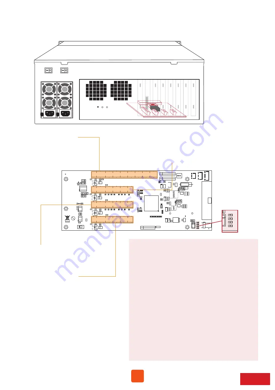
Slot 1: Target card

(already fixed in the chassis)

Slot 2: PCIe ×8 slot

(open-type; supports PCIe card ×16/×8/×4/×1)

RAID card is recommended to be installed in this slot 

    as it’s closest to backplane’s connectors.

Slot 3: PCIe ×8 slot

(closed-type; supports PCIe card ×8/×4/×1)

LED5 for SLOT1

As LED5 illuminates solid blue light, it indicates NP960AG3 target card 
in SLOT#1 is in Gen3 mode. As LED5 blinking blue light, NP960AG3 
target card in SLOT#1 is in Gen2 mode.

LED6 for SLOT2

As LED6 illuminates solid blue light, it indicates the PCIe card in SLOT#2 
is in Gen3 mode. As LED6 blinking blue light, PCIe card in SLOT#2 is in 
Gen2 mode.

LED7 for SLOT3

As LED7 illuminates solid blue light, it indicates the PCIe card in SLOT#3 
is in Gen3 mode. As LED7 blinking blue light, PCIe card in SLOT#3 is in 
Gen2 mode.

LED8 for SLOT4

As LED8 illuminates solid blue light, it indicates the PCIe card in SLOT#4 
is in Gen3 mode. As LED8 blinking blue light, PCIe card in SLOT#4 is in 
Gen2 mode.

Slot 4: PCIe ×8 slot

(open-type; supports PCIe card ×16/×8/×4/×1)

3.  PCIe Expansion Layout

NOTE:

The host computer should have at least one PCIe ×8 
or ×16 slot. There may be PCIe slot which is ×8 or ×16 
physically but ×4 electrically within the host; please 
always install the host card in PCIe slot ×8/×16 electrically 
in the host computer. Check motherboard’s user manual 

to identify the specification.

SLOT4(PCIex8)

SLOT3(PCIex8)

SLOT2(PCIex8)

SLOT1(Upstream PCIex16)

NP951AG3 Rev.A0

1-2

2-3

Compatibility Enable

Standard Mode

OFF

ON

FAN SPEED LOW

FAN SPEED HIGH

OFF

SW1-2

Power on/off by Manual

SW1-1

ON

Power on/off by Host

+

+

+

+

+

+

+

+

+

+

+

+

+

LED 5

LED 6

LED 7

LED 8

Summary of Contents for NA380A-G3

Page 1: ...Second edition Jun 2019 User Manual NA380A G3 4U 24 Bay External PCIe 8 JBOD Storage with PCIe Slot Expansion ...

Page 2: ...1 Unpack the NA380A G3 2 Panel Layout 3 3 5 Operation 9 Questions and Answers 10 4 Build Up Procedure 6 3 PCIe Expansion Layout 5 ...

Page 3: ...ns the following items Netstor NA380A G3 enclosure 1 HDD tray 24 installed in chassis PCIe 3 0 8 host card 1 PCIe 3 0 8 data cable 1 5 meter 1 Internal mini SAS cable 6 Power cord 2 Hard drive mounting screw 96 Key for HDD tray 2 1 HDD power LED 2 HDD Status LED ...

Page 4: ...reen Fail Red stop or low RPM 5 Temperature LED Normal Green Over 55 Red 7 6 6 cm cooling fans 8 External PCIe 8 connector Connecting external PCIe 8 data cable to host computer 3 Mute Button Mute Buzzer Beeping 6 Power cord receptacles ...

Page 5: ...ight PCIe card in SLOT 2 is in Gen2 mode LED7 for SLOT3 As LED7 illuminates solid blue light it indicates the PCIe card in SLOT 3 is in Gen3 mode As LED7 blinking blue light PCIe card in SLOT 3 is in Gen2 mode LED8 for SLOT4 As LED8 illuminates solid blue light it indicates the PCIe card in SLOT 4 is in Gen3 mode As LED8 blinking blue light PCIe card in SLOT 4 is in Gen2 mode Slot 4 PCIe 8 slot op...

Page 6: ...edure 1 Open the chassis by removing the top cover 2 Install RAID card and other third party PCIe cards into proper PCIe slots within NA380A G3 and fix them with screws on the brackets of the cards PCIe Card PCIe Card RAID Card ...

Page 7: ...ckplane to channel 1 4 mini SAS connector on RAID card the second mini SAS connector on backplane to channel 5 8 mini SAS connector on card and subsequently all the way downward to the sixth bottommost mini SAS connector on backplane to channel 21 24 mini SAS connector on RAID card 4 Close the chassis and immobilize it on the server rack or other proper place 17 20 21 24 ...

Page 8: ...e 8 data cable And then connect NA380A G3 with power source 6 Pull out all the HDD trays from the storage enclosure 7 Place hard drives in the trays and fix them with hard drive mounting screws Insert HDD trays back to NA380A G3 storage enclosure Host Computer Power Power ...

Page 9: ... Operation 1 Power on NA333A G3 storage first before powering on the host computer 2 As all the hard drives are identified by the host computer please follow the operational procedure by RAID card Host Computer 2 1 ...

Page 10: ...rd party PCIe card s driver is the same 3 NA380A G3 supports SGPIO what does it mean NA380A G3 chassis supports SGPIO When any HDD fails the red LED indicator on the tray will light The SGPIO function will be effective when the SAS SATA RAID card supports SGPIO function for example Areca s RAID card 4 How do I know the RAID card and the third party PCIe cards installed within NA380A G3 are recogni...

Page 11: ...ease contact your regional distributor or Netstor Technology Taiwan Netstor Technology Co Ltd www netstor com tw 6F No 1 Alley 16 Lane 235 Baoqiao Rd Xindian District New Taipei City 231 45 Taiwan R O C sales netstor com tw 886 2 2917 1500 ...

Reviews: