


Hardware Installation
12
ProSafe™ 24-Port Managed Switch JGSM7224
Connecting to Power and Check the LEDs
The switch does not have an On/Off switch. The only way to apply or remove power is to
connect or disconnect the power cord. Before you connect the power cord, select an AC
outlet that is not controlled by a wall switch (which can turn off power to the switch).
After you select an appropriate outlet, follow these steps to apply AC power:
1.
Connect one end of the AC power adapter cable to the rear of the switch, and the other
end to a grounded three-pronged AC outlet.
2.
Check the Power LED on the front panel of the switch. The LED should light up in the
following sequence:
•
The LED turns yellow as the switch runs a power-on self-test (POST).
•
If the switch passes the test, the LED turns green. The switch is working and ready to
pass data.
•
If the POST fails, the Power LED remains yellow.
If the Power LED does not light up, check that the power cable is plugged in correctly and
that the power source is good. For help with troubleshooting, see
Chapter
3
.”
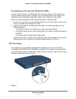
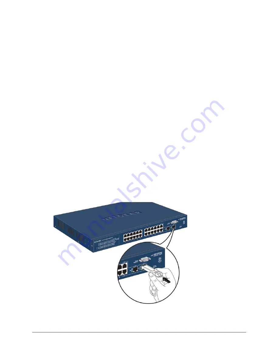
SFP Modules
The module bay accommodates a standard SFP module with an LC connector that is
compatible with the IEEE 802.3z 1000BASE-X standard.
SFP modules are sold separately.
To install an SFP module insert the SFP module into the module bay. Press firmly to ensure
that the module seats into the connector.
Figure 2.


