NETGEAR GS716TP Hardware Installation Manual Download Page 21

Hi-power PoE for surveillance and security

The switch supports both PoE and non-PoE equipment. Model GS716TPP supports a
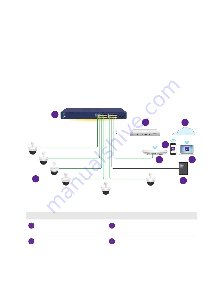
hi-power PoE+ budget, which works well for a surveillance and security configuration.
The following figure shows an example of how you can connect hi-power PoE+
pan-tilt-zoom (PTZ) camera (see device 7) together with a PoE+ WiFi access point (see
device 4) and a non-PoE storage system such as a ReadyNAS (see device 8) to the switch.

You must connect one LAN port on the switch to a LAN port on a router (see device 2
in the following figure) that is connected to the Internet (see 3).

If you use connect a WiFi access point to the switch, you can use a smartphone (see
device 5) or laptop (see device 6) to connect to the WiFi network and use NETGEAR
Insight to discover and manage the switch.

1

2

3

4

5

6

7

8

Figure 6. Sample switch surveillance and security application with model GS716TPP

Device

Number

Device

Number

Smartphone, which allows you to use NETGEAR
Insight to discover and manage the switch in
the network

5

Switch model GS716TPP

1

Laptop, which allows an Insight Premium or
Insight Pro subscriber to use the NETGEAR
Insight Cloud portal to manage the switch.

6

Router

2

Hardware Installation Guide

21

Applications

16-Port Gigabit (Hi-Power) PoE+ Ethernet Smart Managed Pro Switch with 2 SFP Ports

Summary of Contents for GS716TP

Page 1: ...lation Guide 16 Port Gigabit Hi Power PoE Ethernet Smart Managed Pro Switch with 2 SFP Ports and Cloud Management Models GS716TP GS716TPP NETGEAR Inc 350 E Plumeria Drive June 2020 San Jose CA 95134 U...

Page 2: ...y See the regulatory compliance document before connecting the power supply For NETGEAR s Privacy Policy visit https www netgear com about privacy policy By using this device you are agreeing to NETGE...

Page 3: ...or surveillance and security 21 Chapter 4 Installation Step 1 Prepare the site 24 Step 2 Protect against electrostatic discharge 25 Step 3 Unpack the switch 25 Step 4 Mount or place the switch 27 Moun...

Page 4: ...s VoIP phones and IP security cameras so that you do not need to use power supplies for those devices The switch can supply up to 30W PoE IEEE 802 3at to each port The maximum PoE power budget across...

Page 5: ...Interface which lets you access the local browser UI In this mode you can change all settings of the switch For more information about the local browser UI see the user manual which you can download f...

Page 6: ...e Insight app or Insight portal before all Insight manageable device settings are returned to the last configuration saved on the cloud server including the switch password that is the password is res...

Page 7: ...rack mount kit for rack installation Full compatibility with IEEE standards IEEE 802 3 Ethernet IEEE 802 3u 100BASE T IEEE 802 3z Gigabit Ethernet 1000BASE SX LX IEEE 802 3ab 1000BASE T IEEE 802 3i 1...

Page 8: ...ck fire and damage to the equipment observe the following precautions This product is designed for indoor use only in a temperature controlled and humidity controlled environment For more information...

Page 9: ...overs or touching internal components Operate the product only from the type of external power source indicated on the electrical ratings label If you are not sure of the type of power source required...

Page 10: ...ure proper grounding Do not use adapter plugs or remove the grounding prong from a cable If you must use an extension cable use a three wire cable with properly grounded plugs Observe extension cable...

Page 11: ...scribes the switch hardware features The chapter includes the following sections Front panel LEDs Back panel RJ 45 ports for 10 100 1000BASE T Ethernet connectivity SFP uplink port for fiber connectiv...

Page 12: ...716TPP front panel Table 1 Front panel components Description Number Power LED For more information see LEDs on page 13 1 Fan LED For more information see LEDs on page 13 2 PoE Max LED For more inform...

Page 13: ...LED For more information see LEDs on page 13 10 LEDs This section describes the LEDs on the front panel of the switch Table 2 Front panel LEDs Description LED Solid green The switch is powered on and...

Page 14: ...ring PoE Solid green The port is delivering PoE Solid yellow A PoE fault occurred For more information see PoE troubleshooting suggestions on page 34 Off No SFP module link is established Solid green...

Page 15: ...s whether the cable is a straight through or crossover cable Determines whether the link to the attached device requires a normal connection such as when you are connecting the port to a computer or a...

Page 16: ...le must not exceed 5 meters 16 4 feet Multi function Reset button The switch provides a recessed multi function Reset button on the front panel Depending on how long you press the button for details s...

Page 17: ...ault settings but maintain the registration status Press the Reset button for more than 5 seconds but less than 10 seconds Do not press the button for more than 10 seconds Reset the switch to factory...

Page 18: ...s your only network traffic distribution device for PoE and non PoE devices or with 10 Mbps 100 Mbps and 1 Gbps Ethernet and fiber distribution hubs routers access points and other switches This chapt...

Page 19: ...rts to be active simultaneously when the devices correctly report their PoE class to the switch The following table shows the standard power ranges calculated with the maximum cable length of 328 feet...

Page 20: ...a laptop see device 5 or smartphone see device 6 to the WiFi network and use NETGEAR Insight to discover and manage the switch 1 2 3 4 5 6 7 8 9 10 Figure 5 Sample PoE and desktop switching with mode...

Page 21: ...t is connected to the Internet see 3 If you use connect a WiFi access point to the switch you can use a smartphone see device 5 or laptop see device 6 to connect to the WiFi network and use NETGEAR In...

Page 22: ...ice Number PoE pan tilt zoom PTZ cameras 7 Internet 3 ReadyNAS storage system 8 PoE WiFi access point 4 Hardware Installation Guide 22 Applications 16 Port Gigabit Hi Power PoE Ethernet Smart Managed...

Page 23: ...in the following sections Step 1 Prepare the site Step 2 Protect against electrostatic discharge Step 3 Unpack the switch Step 4 Mount or place the switch Optional Step 5 Install SFP transceiver modul...

Page 24: ...source Route cables to avoid sources of electrical noise such as radio transmitters broadcast amplifiers power lines and fluorescent lighting fixtures Cabling Temperature Install the switch in a dry a...

Page 25: ...e antistatic package until you are ready to install it Just before unwrapping the antistatic package discharge static electricity from your body Before moving a sensitive component place it in an anti...

Page 26: ...ht small screws to attach the brackets to the switch four small screws for each side Four large screws to attach the brackets to the rack two screws for each side 3 Two brackets for rack mounting 4 In...

Page 27: ...Insert the screws provided in the product package through each bracket and into the bracket mounting holes in the switch 3 Tighten the screws with a No 2 Phillips screwdriver to secure each bracket 4...

Page 28: ...P transceiver modules The following optional procedure describes how to install an optional SFP transceiver module into one of the SFP ports of the switch Note Contact your NETGEAR sales office to pur...

Page 29: ...ed device to 328 feet 100 meters To connect devices to the switch s RJ 45 Ethernet ports 1 Connect one RJ 45 Ethernet port with an Ethernet cable to your network or connect port 17 or 18 with an SFP t...

Page 30: ...switch 2 Plug the AC power cord into a power source such as a wall socket or power strip 3 Check to see that the LEDs on the front panel of the switch light correctly When you apply power the Power LE...

Page 31: ...t visit netgear com insight and see the NETGEAR knowledge base articles at netgear com support For very basic setup and management you can use the Smart Control Center SCC utility which requires a Win...

Page 32: ...oting This chapter provides information about troubleshooting the switch The chapter includes the following sections Troubleshooting chart PoE troubleshooting suggestions Additional troubleshooting su...

Page 33: ...evice to any other networked device After you connect to the switch web management interface you can configure the Spanning Tree Protocol STP to prevent network loops One possible cause is that a broa...

Page 34: ...h permits The maximum level is 15 4W for a PoE connection or 30W for a PoE connection The PoE current on the port exceeded the classification limit of the PD Restart the switch to see if the condition...

Page 35: ...the other end of the link supports autonegotiation If the device does not support autonegotiation the switch determines only the speed correctly and the duplex mode defaults to half duplex The Gigabit...

Reviews: